Engine heat management system and charging vehicle comprising same

A thermal management system and engine technology, used in engine cooling, engine components, machines/engines, etc., can solve problems such as engine derating, over-temperature warning, and inability to work, so as to improve performance and efficiency and prolong service life. , the effect of simple structure

Pending Publication Date: 2018-12-07
NIO ANHUI HLDG CO LTD
View PDF9 Cites 8 Cited by
  • Summary
  • Abstract
  • Description
  • Claims
  • Application Information

AI Technical Summary

Problems solved by technology

[0003] However, since the working conditions and working conditions of the modified engine have changed greatly compared with those before the modification, the requirements of the engine for the thermal management system have also undergone great changes. For example, the high-power operation of the engine before modification When the vehicle is running at high speed, it provides a large amount of cooling air for the engine during operation, but after being converted into a charging car to generate electricity for parking, it cannot provide a large amount of cooling air generated by the high

Method used


Image

  • Engine heat management system and charging vehicle comprising same
  • Engine heat management system and charging vehicle comprising same
  • Engine heat management system and charging vehicle comprising same

Examples


Example Embodiment

[0059] Example one

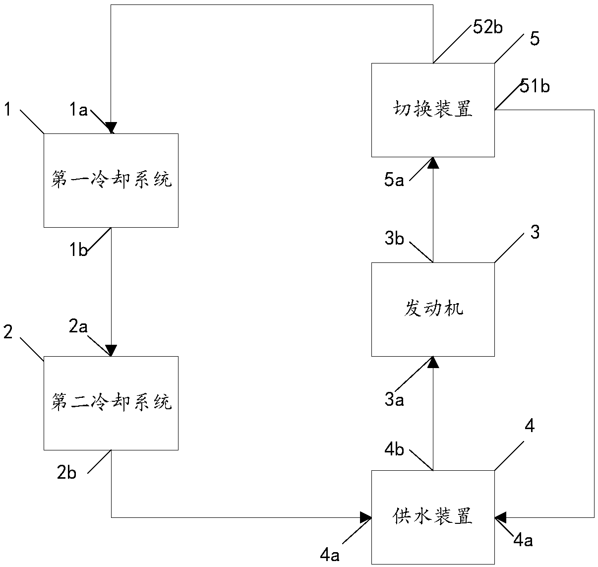
[0060] Such as figure 1 As shown, the cooling circuit includes a first cooling system 1 and a second cooling system 2 connected in series. The second liquid outlet 52b of the switching device 5 is connected with the liquid inlet 1a of the first cooling system, and the liquid outlet 1b of the first cooling system is connected with the liquid inlet 2a of the second cooling system. The liquid outlet 2b is connected with the liquid inlet 4a of the water supply device, and the engine 3, the switching device 5, the water supply device 4, the first cooling system 1 and the second cooling system 2 constitute a cooling cycle.

[0061] During the normal driving of the charging car, figure 1 The engine thermal management system shown does not change the control strategy of the original cooling system of the vehicle, and turns off the cooling devices in the second cooling system 2, such as water pumps, fans, radiators, etc., so that the second cooling system 2 only provide...

Example Embodiment

[0063] Embodiment two

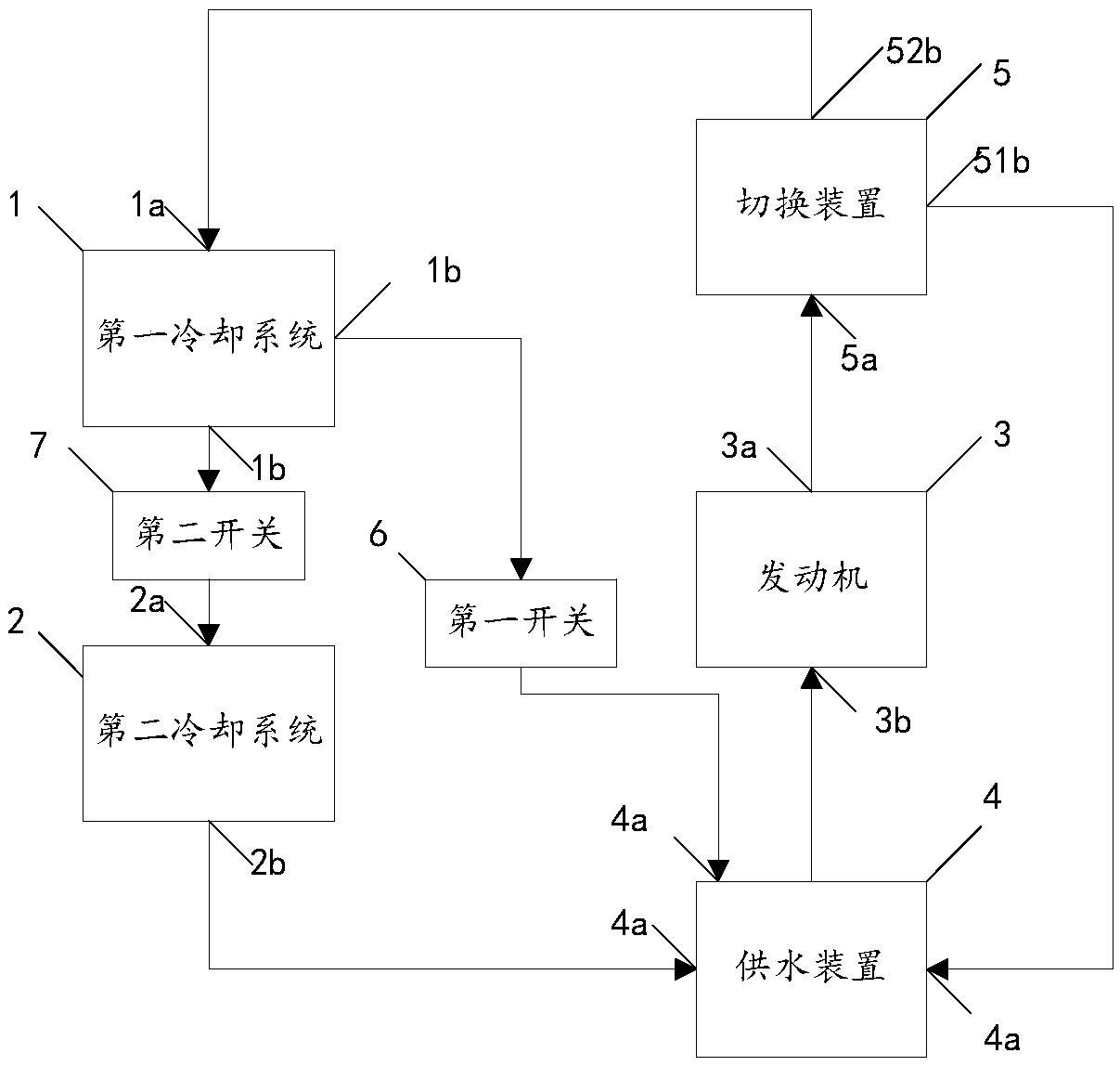
[0064] The first cooling system 1 and the second cooling system 2 are connected in series to the cooling circuit. During the normal driving of the charging car, the second cooling system 2 only provides the circulation function of the cooling liquid, but the cooling liquid flows through the second cooling system 2. There will still be a certain temperature change. When the temperature change range is small, it will not affect the cooling circuit in the normal driving process of the charging car, but when the change range is large, it will affect the cooling circuit in the normal driving process of the charging car. The operation of the engine will affect the temperature control of the engine 3. As a variation of the embodiment, such as figure 2 The engine thermal management system shown can effectively avoid the occurrence of the above situation. The cooling circuit of the engine thermal management system also includes a first switch 6 and a second switch...

Example Embodiment

[0067] Embodiment three

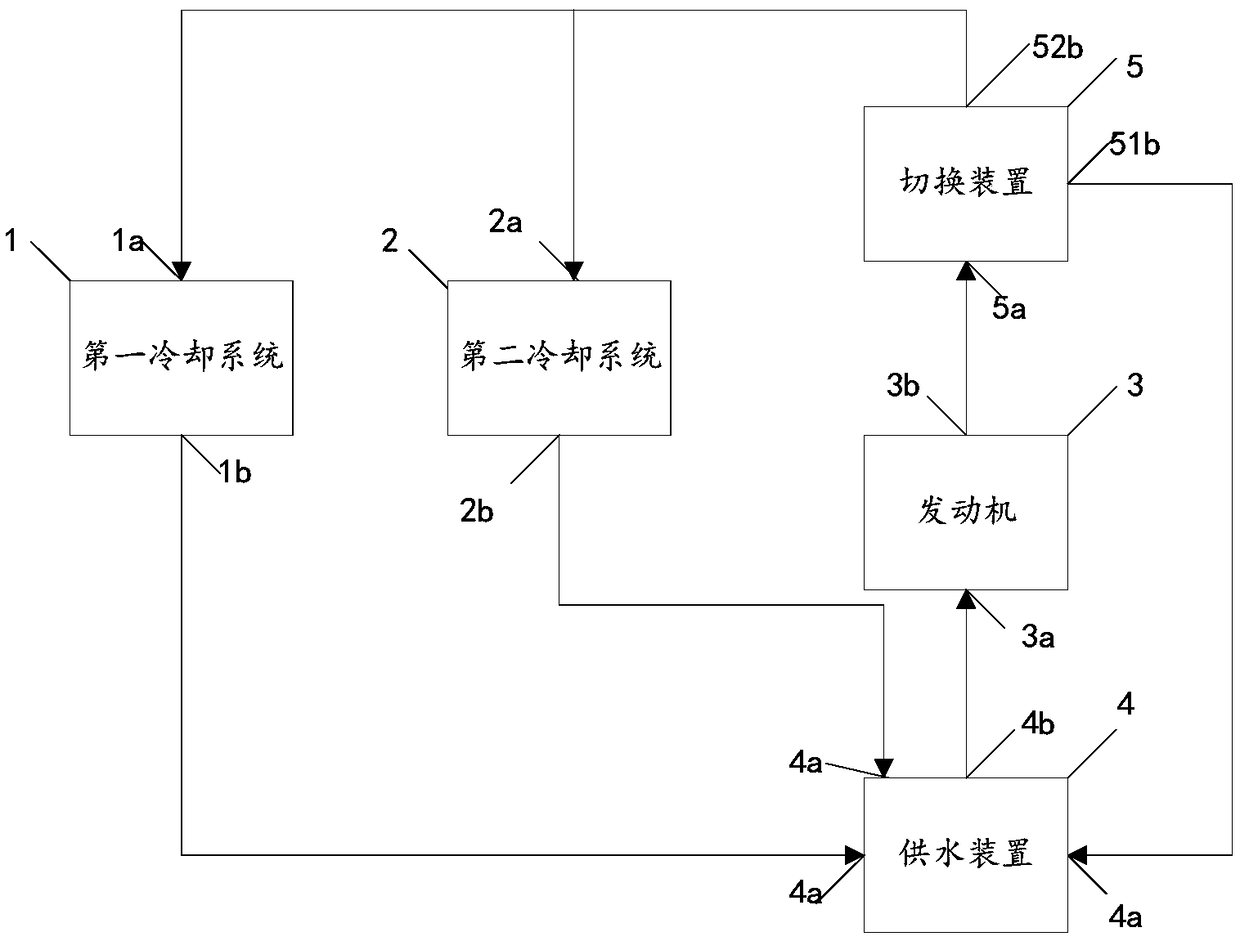
[0068] Such as image 3 As shown, the cooling circuit includes a first cooling system 1 and a second cooling system 2 connected in parallel. The second liquid outlet 52b of the switching device 5 is respectively connected with the liquid inlet 1a of the first cooling system and the liquid inlet 2a of the second cooling system. The liquid outlet 1b of the first cooling system and the outlet of the second cooling system are respectively connected. The liquid ports 2b are respectively connected with the liquid inlet 4a of the water supply device, and the engine 3, the switching device 5, the water supply device 4, the first cooling system 1 and the second cooling system 2 constitute a cooling cycle.

[0069] During the normal driving of the charging car, image 3 The engine thermal management system shown does not change the control strategy of the original cooling system of the vehicle, and turns off the cooling devices in the second cooling system 2, such a...


PUM


Abstract

The invention relates to an engine heat management system and a charging vehicle comprising the same. The engine heat management system comprises a cooling loop used for cooling an engine when the temperature of the engine is higher than first preset temperature. The cooling loop comprises a first cooling system and a second cooling system, and the second cooling system and the first cooling system are connected into the cooling loop in series or in parallel. The engine heat management system can meet the charging requirement of the charging vehicle under various working conditions, and it isensured that the charging vehicle runs safely, efficiently and economically.

Description

technical field [0001] The invention relates to the technical field of engine thermal management, in particular to an engine thermal management system and a charging vehicle including the same. Background technique [0002] With the rapid development of electric vehicles, the demand for charging is increasing day by day. In order to meet the diverse charging needs of customers, mobile charging vehicles (hereinafter referred to as "charging vehicles") have emerged as the times require, and most charging vehicles use the "power generation-charging" method. Charging vehicles can be converted based on rear-drive light commercial vehicles, usually by installing a complete set of diesel generators inside the vehicle to generate electricity. However, since the chassis of the vehicle, the space of the compartment and the load of the vehicle are small, a generator with a large volume and weight cannot be installed, so the power generation is generally small, which is far from meeting...

Claims


Application Information

Patent Timeline
IPC IPC(8): F01P3/20F01P7/16F01P5/02F01P5/10F01P11/00F02B63/04
CPCF01P3/20F01P5/02F01P5/10F01P7/16F01P11/00F02B63/04
Inventor 武明岩杨昌城何旭谭卓辉魏涛张书常艾永夫
Owner NIO ANHUI HLDG CO LTD
Why Eureka
Try Eureka