Turbulent-laminar-flow conversion device at outlet of cutting fluid circulating pool

A technology of conversion device and circulation pool, which is applied in the direction of fluid flow, metal processing machinery parts, maintenance and safety accessories, etc., and can solve problems such as wear, deterioration and odor of cutting fluid, mechanical abrasion, etc.

Pending Publication Date: 2018-12-07
逸乐(廊坊)环保科技有限公司
View PDF0 Cites 2 Cited by
  • Summary
  • Abstract
  • Description
  • Claims
  • Application Information

AI Technical Summary

Problems solved by technology

[0002] During the processing of the workpiece by the machine tool, wear and high temperature will be generated due to high-speed friction between the tool and the workpiece. In order to reduce friction and reduce the high temperature generated by friction, when processing the workpiece, it is necessary to continuously spray the contact parts of the tool and the workpiece Cutting fluid, cutting fluid is recycled through the cutting fluid circulation system. Due to leakage and other reasons, it is inevitable that some machine tool lubricating oil and hydraulic oil will be mixed into the cutting fluid circulation system. As the cutting fluid circulation time continues to increase, The content of waste oil (machine lubricating oil and hydraulic oil) in the cutting fluid will increase, which will reduce the use function of the cutting fluid, weaken the lubrication effect, and will cause mechanical abrasion and wear, so that the precision of the processed workpiece cannot reach To meet the design requirements, at the same time, the high temperature generated by the friction between the tool and the workpiece will increase the temperature of the cutting fluid, thereby breeding anaerobic bacteria, causing the cutting fluid to deteriorate and smell, polluting the surrounding environment and affecting the health of workers

Method used


Image

  • Turbulent-laminar-flow conversion device at outlet of cutting fluid circulating pool
  • Turbulent-laminar-flow conversion device at outlet of cutting fluid circulating pool
  • Turbulent-laminar-flow conversion device at outlet of cutting fluid circulating pool

Examples


Embodiment Construction

[0035] The present invention will be further described in detail below in conjunction with the accompanying drawings and specific embodiments.

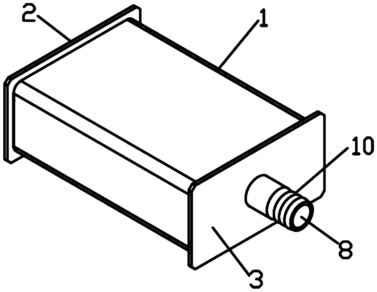
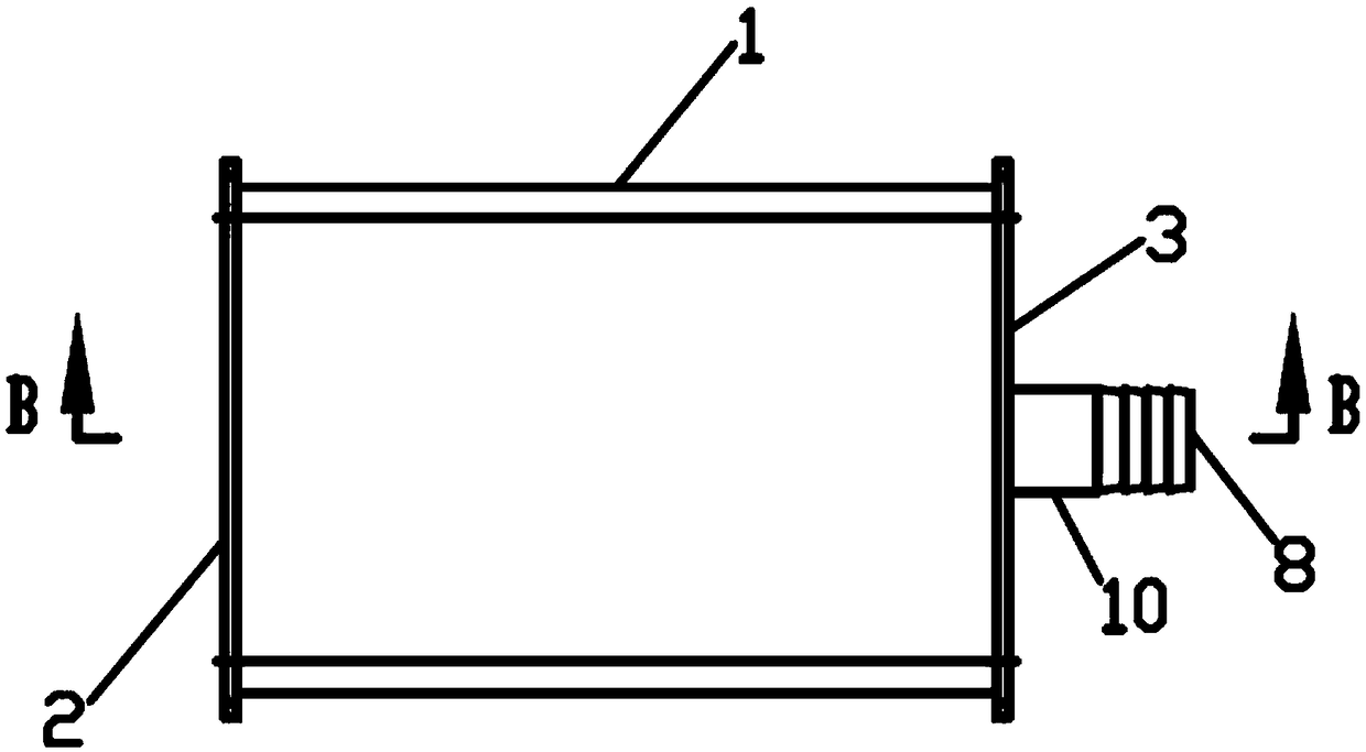
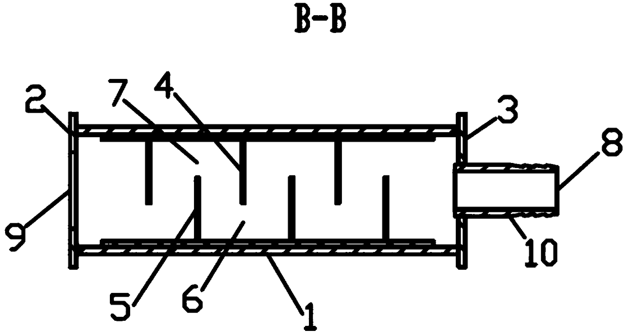
[0036] Depend on Figure 1-3 As can be seen from the illustrated embodiment, this embodiment includes a rectangular tube 1, a liquid outlet 9, a liquid inlet 8, a set of downward flow damping sheets 4 and a set of upward flow damping sheets 5, and the inner chamber of the rectangular pipe 1 The length is more than three times its height, the width value of the inner cavity section of the rectangular tube 1 > the height value of the inner cavity section of the rectangular tube 1, the liquid outlet 9 is set at the front end of the rectangular tube 1, and the liquid inlet 8 is set at the rectangular tube 1 The rear end, the cross-sectional area of ​​the liquid outlet 9 is more than three times the cross-sectional area of ​​the liquid inlet 8, and each downward guide damping plate 4 and each upward guide damping plate 5 are alternately ar...


PUM


Abstract

The invention discloses a turbulent-laminar-flow conversion device at an outlet of a cutting fluid circulating pool. The turbulent-laminar-flow conversion device comprises a rectangular tube, a liquidoutlet, a group of downward diversion damping sheets of the liquid inlet and a group of upward diversion damping sheets of the liquid inlet. The liquid inlet is formed in the rear end of the rectangular tube. The sectional area of the liquid outlet is more than three times of the sectional area of the liquid inlet. Each downward diversion damping sheet and each upward diversion damping sheet arealternately arranged at an interval and are parallel to the cross section of the rectangular tube. The upper end edge of each downward diversion damping sheet is connected with the upper cavity wall of the rectangular tube. The left end edge and the right end edge of each downward diversion damping sheet are correspondingly connected with the upper part of the left side wall and the upper part ofthe right side wall of the rectangular tube. The lower end edge of each upward diversion damping sheet is connected with the lower cavity wall of the rectangular tube, and the left end edge and the right end edge of each upward diversion damping sheet are correspondingly connected with the lower part of the left side wall and the lower part of the right side wall of the rectangular tube. The turbulent-laminar-flow conversion device has the beneficial effects of being small in size, reliable to work, low in manufacturing cost and the like.

Description

technical field [0001] The invention relates to a turbulent flow-laminar flow conversion device at the outlet of a cutting fluid circulation pool. Background technique [0002] During the processing of the workpiece by the machine tool, wear and high temperature will be generated due to high-speed friction between the tool and the workpiece. In order to reduce friction and reduce the high temperature generated by friction, when processing the workpiece, it is necessary to continuously spray the contact parts of the tool and the workpiece Cutting fluid, cutting fluid is recycled through the cutting fluid circulation system. Due to leakage and other reasons, it is inevitable that some machine tool lubricating oil and hydraulic oil will be mixed into the cutting fluid circulation system. As the cutting fluid circulation time continues to increase, The content of waste oil (machine lubricating oil and hydraulic oil) in the cutting fluid will increase, which will reduce the use f...

Claims


Application Information

Patent Timeline
Patent Type & Authority Applications(China)
IPC IPC(8): F15D1/00B23Q11/10
CPCF15D1/0025B23Q11/10F15D1/0045
Inventor 王丹史昊天杨俊学张敬爽王成龙丰志良苏艳杰刘一飞程磊
Owner 逸乐(廊坊)环保科技有限公司
Why Eureka
Try Eureka