Damping device for mechanical equipment

A technology of shock absorbing devices and mechanical equipment, which is applied in the direction of mechanical equipment, shock absorbers, springs/shock absorbers, etc., and can solve problems such as poor protection of shock absorbing mechanisms, mechanical equipment damage, and poor buffer protection effects , to achieve good protection effect, reduce lateral impact force and avoid misalignment

Inactive Publication Date: 2018-12-07
文芙生
View PDF0 Cites 2 Cited by
  • Summary
  • Abstract
  • Description
  • Claims
  • Application Information

AI Technical Summary

Problems solved by technology

[0003] However, there are some deficiencies in the existing shock absorbing devices for mechanical equipment during use. At present, the shock absorbing devices for mechanical equipment are basically for vertical buffer protection. When the force is high, the protection effect of the shock-absorbing mechanism is not good, which causes damage to the mechanical equipment.

Method used


Image

  • Damping device for mechanical equipment
  • Damping device for mechanical equipment
  • Damping device for mechanical equipment

Examples


Embodiment 1

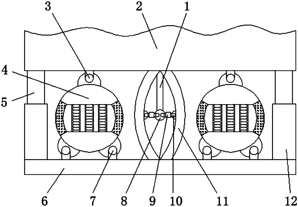
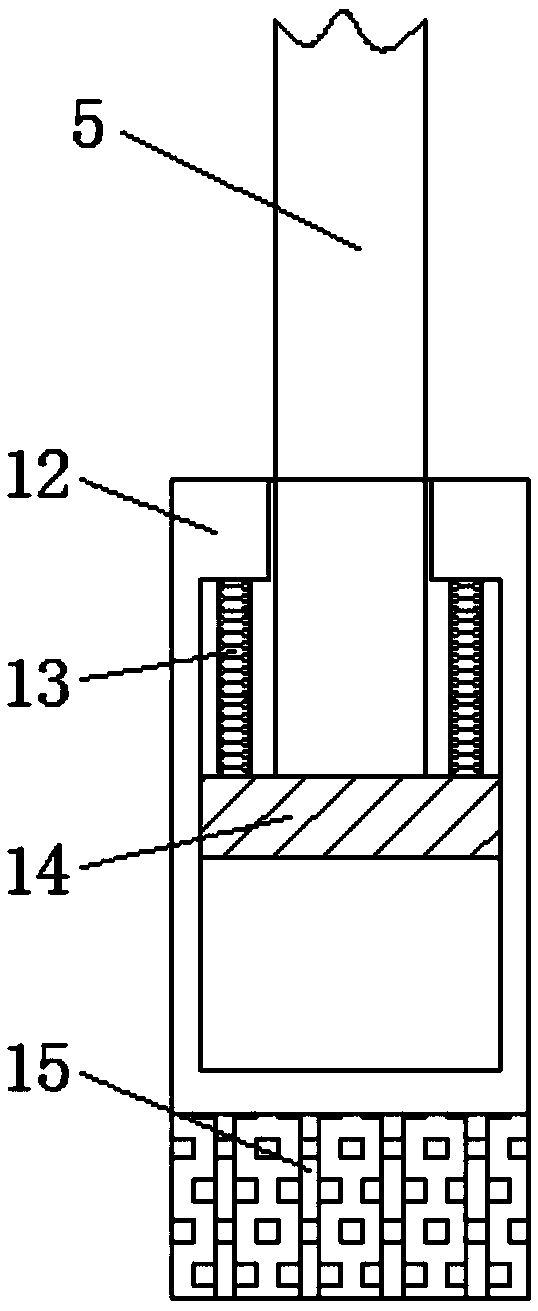
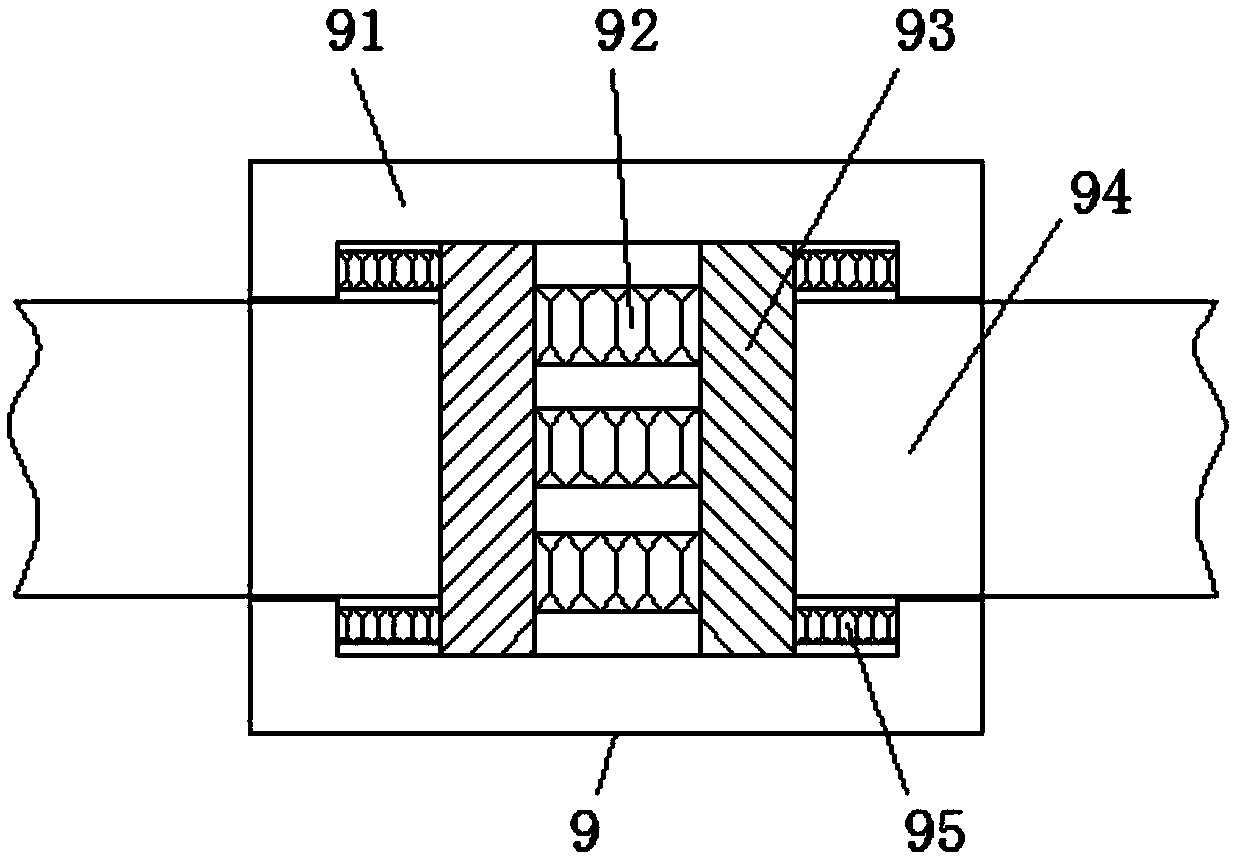
[0025] Embodiment one: refer to Figure 1-3 , a shock-absorbing device for mechanical equipment, including an upper fixing seat 2 and a lower fixing seat 6, the four corners of the top of the lower fixing seat 6 are welded with fixed sleeves 12, and the bottom of the fixed sleeve 12 is provided with a SH180X1480 hydraulic cylinder 15. The inside of the fixed sleeve 12 is covered with a sealing plate 14, the top of the sealing plate 14 is welded to the upper fixing seat 2 through the connecting rod 5 passing through the fixing sleeve 12, and the middle position of the top of the lower fixing seat 6 is symmetrically arranged. The arc-shaped elastic plate 11 is connected with the upper fixing seat 2, and the bottom of the upper fixing seat 2 is located at the intersection of the two arc-shaped elastic plates 11 and is connected with a fixed disc 8 through the fixing rod 1, wherein the center line of the two arc-shaped elastic plates 11 On the same level as the fixed disk 8, the f...

Embodiment 2

[0026] Embodiment two: refer to figure 2 The outer side of the connecting rod 5 on the sealing plate 14 is elastically connected to the top of the fixed sleeve 12 through a plurality of first tension springs 13. This structure can prevent the impact force received between the connecting rod 5 and the fixed sleeve 12 from being relatively large. Large, falling off occurs, and at the same time, buffer protection can be performed between the sealing plate 14 and the fixed sleeve 12 .

Embodiment 3

[0027] Embodiment three: refer to figure 1 with Figure 4 , the top of the lower fixing seat 6 is located on both sides of the arc-shaped elastic plate 11 and is flexibly connected with the buffer sphere 4 through the second movable connection card 7, and the top center of the buffer sphere 4 is movable with the upper fixing seat 2 through the first movable connection card 3 The connection can make the buffer sphere 4 deform in different directions, so that the effect of shock absorption is better. The inside of the buffer sphere 4 is a hollow structure, and an elastic connecting ring 42 is arranged at the middle position of the outer wall of the buffer sphere 4, and the buffer sphere The inside of 4 is connected to both ends by a buffer spring 41, and there are two second movable connection cards 7 located at the bottom of the buffer sphere 4, and the two second movable connection cards 7 are symmetrical about the vertical midline of the buffer sphere 4, and the upper fixed ...


PUM


Abstract

The invention discloses a damping device for mechanical equipment. The damping device comprises an upper fixed seat and a lower fixed seat. Fixed sleeves are welded to the four corners of the top of the lower fixed seat, and SH180X1480 hydraulic cylinders are arranged at the bottoms of the fixed sleeves. Sealing plates are sleeved with the fixed sleeves, and the tops of the sealing plates are welded to the upper fixed seat through connecting rods penetrating the fixed sleeves. According to the damping device, arc-shaped elastic plates are symmetrically arranged between the upper fixed seat andthe lower fixed seat, and a fixed disc is connected to the position, between the two arc-shaped elastic plates, of the bottom of the upper fixed seat through a fixed rod. The two sides of the fixed disc are connected with the arc-shaped elastic plates through adjusting mechanisms. According to the structure, on one hand, the arc-shaped elastic plates cannot greatly deform during buffering protection, and the buffering protection effect is good; and on the other hand, the transverse impact force of the mechanical equipment can be reduced.

Description

technical field [0001] The invention relates to the technical field of mechanical equipment, in particular to a shock absorbing device for mechanical equipment. Background technique [0002] The structure of the shock absorber is that the piston rod with the piston is inserted into the cylinder, and the cylinder is filled with oil. There is an orifice on the piston, so that the oil in the two spaces separated by the piston can complement each other. Damping is produced when viscous oil passes through the orifice, the smaller the orifice, the greater the damping force, and the greater the viscosity of the oil, the greater the damping force. If the size of the orifice remains the same, when the shock absorber works fast, excessive damping will affect the absorption of shock. Therefore, a disc-shaped leaf spring valve is set at the outlet of the orifice. When the pressure increases, the valve is pushed open, the opening of the orifice becomes larger, and the damping becomes s...

Claims


Application Information

Patent Timeline
Patent Type & Authority Applications(China)
IPC IPC(8): F16F13/00
CPCF16F13/007
Inventor 文芙生
Owner 文芙生
Why Eureka
Try Eureka