Autorotation equipment for motorcycle hub coating

A motorcycle and wheel hub technology is applied in the field of rotation equipment for motorcycle wheel hub coating, which can solve the problems of high workpiece coating defect rate, different rotation speeds, unstable workpiece rotation, etc., so as to improve the processing yield and increase Stability, the effect of protecting the internal structure of the rack

Pending Publication Date: 2022-02-18
东莞市新力光表面处理科技有限公司
View PDF0 Cites 0 Cited by
  • Summary
  • Abstract
  • Description
  • Claims
  • Application Information

AI Technical Summary

Problems solved by technology

Due to the fact that the material of the workpiece is a heavy metal part, the rotation of the workpiece in the existing equipment is unstable during the painting process, and it often swings from side to side and the rotation speed is different, which eventually leads to a high rate of defective coating of the workpiece

Method used


Image

  • Autorotation equipment for motorcycle hub coating
  • Autorotation equipment for motorcycle hub coating
  • Autorotation equipment for motorcycle hub coating

Examples


Embodiment 1

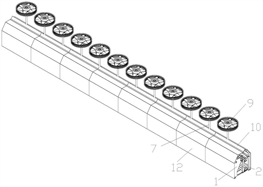
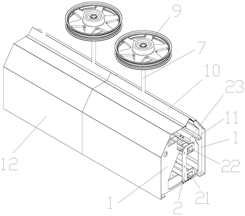
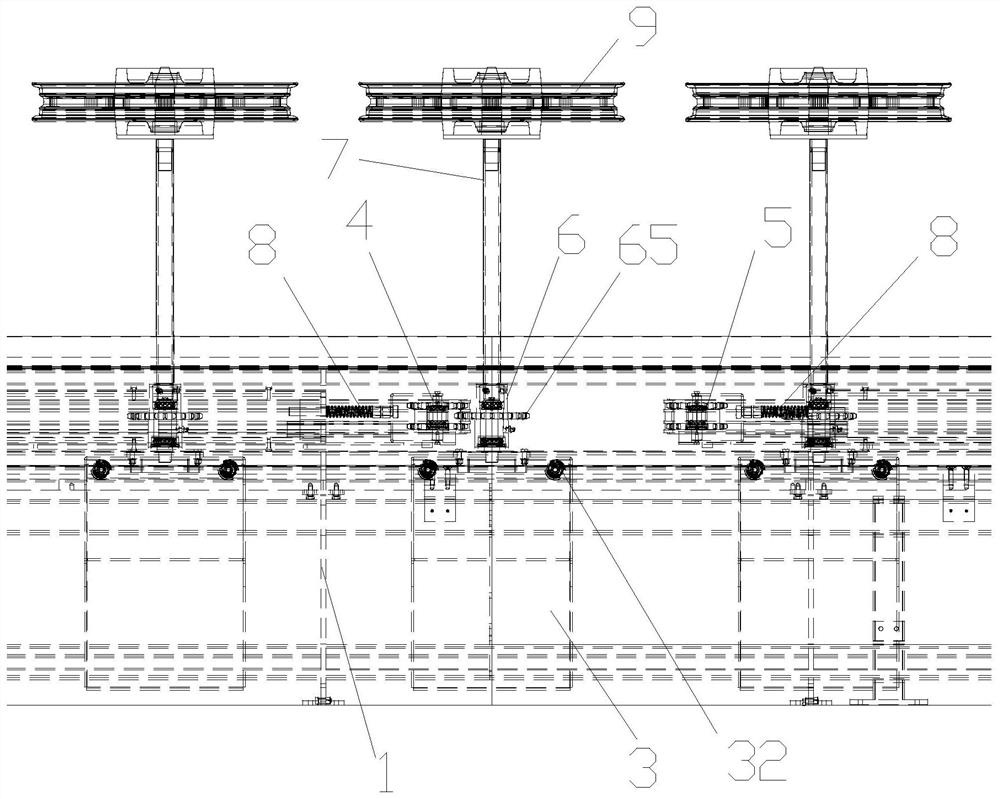
[0022] Embodiment 1: as Figure 1-5 As shown, a kind of autorotation equipment for motorcycle wheel hub coating comprises frame 1, and described frame 1 is the long frame of assembly line type, and frame 1 is provided with guide rail frame 2, and a plurality of trolleys 3 are arranged at intervals and installed on On the guide rail frame 2 and can move horizontally in the frame 1 along the guide rail frame 2, the upper part of the frame 1 is provided with a clockwise rotation power mechanism 4 and an anticlockwise rotation power mechanism 5 successively along the direction of travel of the dolly 3.

[0023] Both sides of the traveling direction of the trolley 3 are provided with vehicle body stabilizing plates 11 mounted on the frame 1; the lower part of the guide rail frame 2 is provided with a lower guide rail groove 21, the middle part is provided with a traction chain groove 22, and the upper part is provided with a strip-shaped The upper guide rail 23; the upper part of t...

Embodiment 2

[0030] Embodiment 2: as Figure 1-4 As shown, a kind of autorotation equipment for motorcycle wheel hub coating comprises frame 1, and described frame 1 is the long frame of assembly line type, and frame 1 is provided with guide rail frame 2, and a plurality of trolleys 3 are arranged at intervals and installed on On the guide rail frame 2 and can move horizontally in the frame 1 along the guide rail frame 2, the upper part of the frame 1 is provided with a clockwise rotation power mechanism 4 and an anticlockwise rotation power mechanism 5 successively along the direction of travel of the dolly 3.

[0031] Both sides of the traveling direction of the trolley 3 are provided with vehicle body stabilizing plates 11 mounted on the frame 1; the lower part of the guide rail frame 2 is provided with a lower guide rail groove 21, the middle part is provided with a traction chain groove 22, and the upper part is provided with a strip-shaped The upper guide rail 23; the upper part of t...


PUM


Abstract

The invention discloses an autorotation equipment for motorcycle hub coating. The autorotation equipment comprises a rack, a guide rail frame and a trolley; an upper guide rail base, a sliding block and a trolley body stabilizing bearing are designed on the trolley, the stability of a workpiece in the advancing process and the autorotation process is improved, and thus the machining yield of the workpiece is improved; a clockwise autorotation power mechanism and an anticlockwise autorotation power mechanism are arranged, and in the advancing process of the trolley, clockwise or anticlockwise rotation of the workpiece is achieved through automatic meshing of a transmission gear; tensioning adjusting assemblies on the clockwise autorotation power mechanism and the anticlockwise autorotation power mechanism can adjust the connecting gap between a transmission chain and the transmission gear, so that transverse impact on a driven shaft is minimum, and operation is more stable. A flexible protective cover is arranged, a closed cavity structure is formed in the rack, a positive pressure cavity is formed in the closed cavity structure through inflation, paint or paint mist can be prevented from entering the rack, and the internal structure of the rack is protected; and a plurality of bearings and step-shaped structures are arranged in the driven shaft, so that the stability is improved.

Description

technical field [0001] The invention belongs to the technical field of motorcycle hub coating equipment, and in particular relates to a self-rotating equipment for motorcycle hub coating. Background technique [0002] In the coating process of motorcycle wheels (hereinafter referred to as "workpieces"), there are processes such as dust removal, painting, and baking, which require a conveying mechanism to continuously transport the workpieces to each process station. The workpiece needs to be continuously and stably rotated clockwise or counterclockwise during painting to improve the coverage and quality of the paint on the surface of the workpiece. Due to the fact that the material of the workpiece is a heavy metal part, the rotation of the workpiece in the existing equipment is unstable during the painting process, and it often swings from side to side and the rotation speed is different, which eventually leads to a high rate of defective coating of the workpiece. Content...

Claims


Application Information

Patent Timeline
Patent Type & Authority Applications(China)
IPC IPC(8): B05B13/02B05B15/00
CPCB05B13/0235B05B15/00
Inventor 何光华王俊
Owner 东莞市新力光表面处理科技有限公司
Why Eureka
Try Eureka