Gearbox for vehicle engine transmission

A transmission gear and engine technology, which is applied in the direction of transmission, transmission parts, gear transmission, etc., can solve the problems of cumbersome speed regulation, friction and vibration of gear teeth, etc., and achieve the effect of reducing noise pollution, reducing vibration and reducing kinetic energy loss

Inactive Publication Date: 2018-12-07
浙江合奥机械科技有限公司
View PDF0 Cites 3 Cited by
  • Summary
  • Abstract
  • Description
  • Claims
  • Application Information

AI Technical Summary

Problems solved by technology

[0004] The purpose of the present invention is to provide a gear box for vehicle engine transmission to solve the problems of gear tooth frictio

Method used


Image

  • Gearbox for vehicle engine transmission
  • Gearbox for vehicle engine transmission
  • Gearbox for vehicle engine transmission

Examples


Embodiment Construction

[0020] The following will clearly and completely describe the technical solutions in the embodiments of the present invention with reference to the accompanying drawings in the embodiments of the present invention. Obviously, the described embodiments are only some, not all, embodiments of the present invention. Based on the embodiments of the present invention, all other embodiments obtained by persons of ordinary skill in the art without making creative efforts belong to the protection scope of the present invention.

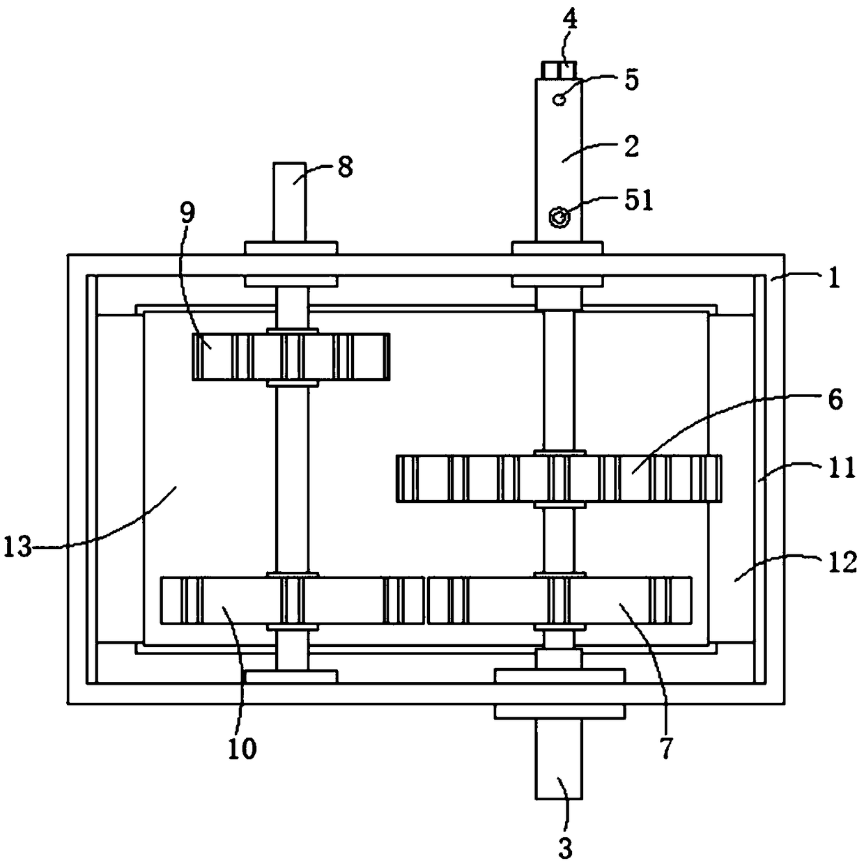
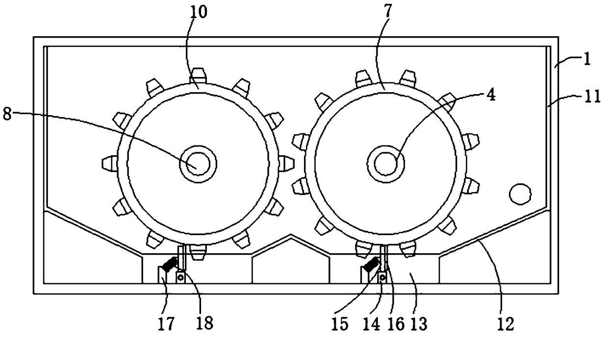
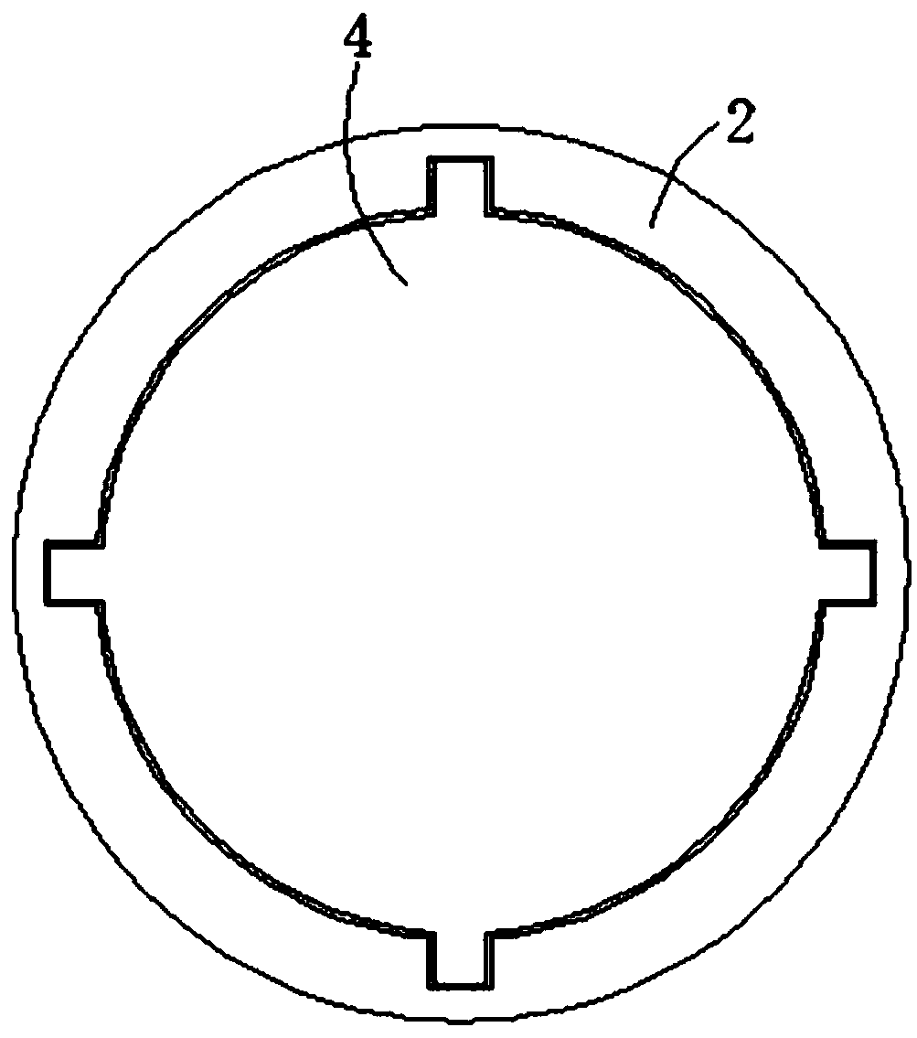
[0021] see Figure 1-Figure 5 As shown, the present invention provides the following technical solution: a gear box for vehicle engine transmission, including a box body 1, a first rotating shaft sleeve 2 runs through one side of the outer wall of the box body 1, and a second rotating shaft runs through the other side outer wall Sleeve 3, an output shaft 4 is arranged between the first shaft sleeve 2 and the second shaft sleeve 3, and a fixed pin hole 5 is pro...


PUM


Abstract

The invention discloses a gearbox for vehicle engine transmission. The gearbox comprises a box body, a first rotary shaft sleeve penetrates through the outer wall of one side of the box body, a secondrotary shaft sleeve penetrates through the outer wall of the other side of the box body, an output rotating shaft is arranged between the first rotary shaft sleeve and the second rotary shaft sleeve,a fixing pin hole is formed in the outer wall of one side of the output rotating shaft, a fixing pin is arranged inside the fixing pin ole, the outer wall of the output rotating shaft is sleeved witha first transmission gear and a second transmission gear, and the first transmission gear is located on one side of the second transmission gear. By sliding the output rotating shaft, the first transmission gear is engaged with a first engagement gear, and the second transmission gear is engaged with a second engagement gear, so that the rotating speed of the output rotating speed is convenientlyadjusted, the output rotating speed of an engine can be adjusted as needed, the gearbox is applicable to different environments, kinetic energy consumption is reduced, and energy conservation and environmental protection are achieved.

Description


Claims


Application Information

Patent Timeline
Owner 浙江合奥机械科技有限公司
Why Eureka
Try Eureka