Al technical title is built by PatSnap Al team. It summarizes the technical point description of the patent document.
A power transmission device, a composite technology, which is applied to multi-transmission ratio transmission devices, transmission devices, gear transmission devices, etc., can solve the problems of inability to adjust the power output and low efficiency, and achieve accurate transmission power and high transmission efficiency. , the effect of reducing wear
Inactive Publication Date: 2018-12-07
陶武佑
View PDF0 Cites 0 Cited by
Summary
Abstract
Description
Claims
Application Information
AI Technical Summary
This helps you quickly interpret patents by identifying the three key elements:
Problems solved by technology
Method used
Benefits of technology
Problems solved by technology
[0002] A power transmission device is a device used to transmit power. Generally speaking, a power transmission device can be used on a car engine or some other power devices. The existing power transmission device is inefficient and often uses a The output shaft is used for power output, and the degree of power output cannot be adjusted according to needs
Method used
Image
Click on the blue label to locate the original text in one second.
Reading with bidirectional positioning of images and text.
Examples
Embodiment Construction
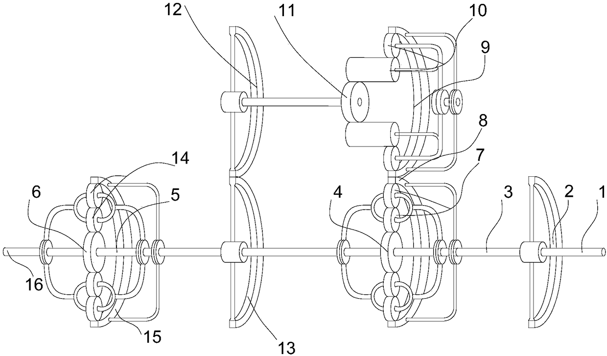
[0016] The present invention will be described in further detail below in conjunction with the accompanying drawings.
[0017] figure 1 It schematically shows the structure of a compound power transmission device according to an embodiment of the present invention.
[0018] Such as figure 1 as shown, figure 1 All the rotating shafts and connecting shafts are drawn in the same scale, but it does not represent their actual size, and two components that need to be connected by shafts can be connected in the following ways, (1) directly connected by connecting shafts; (2) Use the connecting shaft to pass through other components. Connects two components that need to be joined together.
[0019] Each gear can be connected with the shaft by fixed connection or rotation connection. Each gear has its own shaft, and two or more gears that need to rotate synchronously (simultaneously, in the same direction, at the same speed) can have the same shaft, and the rest of the gears have ...
PUM
Abstract
The invention discloses a composite power transmission device. The composite power transmission device comprises a power input shaft, an input gear, a first rotating shaft, an intermediate gear, a second rotating shaft, an output gear, a first planetary gear, a first planetary gear set, a first big gear, a second big gear, a second planetary gear set, a pinion, a third big gear, a fourth big gear,a third planetary gear set, an output gear, a fifth big gear and an output shaft. The composite power transmission device has the following advantages that (1) compared with traditional power transmission only using the output shaft, the composite power transmission device conducts power transmission through a multistage mode, and thus power transmission can be more accurate; (2) required power transmission can be achieved by changing the transmission ratio between all the gears; and (3) in the composite power transmission device, the multiple gears and the multiple gear sets are arranged, therefore, the speed can be changed in the transmission process, rigid force is small, and the longer service life can be achieved.
Description
technical field [0001] The invention relates to a compound power transmission device. Background technique [0002] A power transmission device is a device used to transmit power. Generally speaking, a power transmission device can be used on a car engine or some other power devices. The existing power transmission device is less efficient and often uses a The output shaft is used for power output, and the degree of power output cannot be adjusted according to needs. Contents of the invention [0003] According to one aspect of the present invention, a compound power transmission device is provided to solve at least one of the above technical problems. [0004] According to one aspect of the present invention, a compound power transmission device is provided, including a power input shaft, an input gear, a first rotating shaft, an intermediate gear, a second rotating shaft, an output gear, a first planetary gear, a first planetary gear set, The first large gear, the seco...
Claims
Application Information
Patent Timeline
Application Date:The date an application was filed.
Publication Date:The date a patent or application was officially published.
First Publication Date:The earliest publication date of a patent with the same application number.
Issue Date:Publication date of the patent grant document.
PCT Entry Date:The Entry date of PCT National Phase.
Estimated Expiry Date:The statutory expiry date of a patent right according to the Patent Law, and it is the longest term of protection that the patent right can achieve without the termination of the patent right due to other reasons(Term extension factor has been taken into account ).
Invalid Date:Actual expiry date is based on effective date or publication date of legal transaction data of invalid patent.