Eureka AIR delivers breakthrough ideas for toughest innovation challenges, trusted by R&D personnel around the world.

Electric control flow valve

A flow valve and electric control technology, applied in the field of flow valve, can solve the problems of inconvenient fluid flow control and complex flow valve structure, etc., and achieve the effect of reasonable structure

Inactive Publication Date: 2018-12-07
王红军
View PDF7 Cites 2 Cited by
  • Summary
  • Abstract
  • Description
  • Claims
  • Application Information

AI Technical Summary

Problems solved by technology

[0004] In view of this, the object of the present invention is to provide an electronically controlled flow valve to solve the problems of the existing flow valve with complex structure and inconvenient fluid flow control.

Method used


Image

  • Electric control flow valve

Examples


Embodiment Construction

[0016] The present invention will be further explained below in conjunction with specific embodiments, but the present invention is not limited thereto.

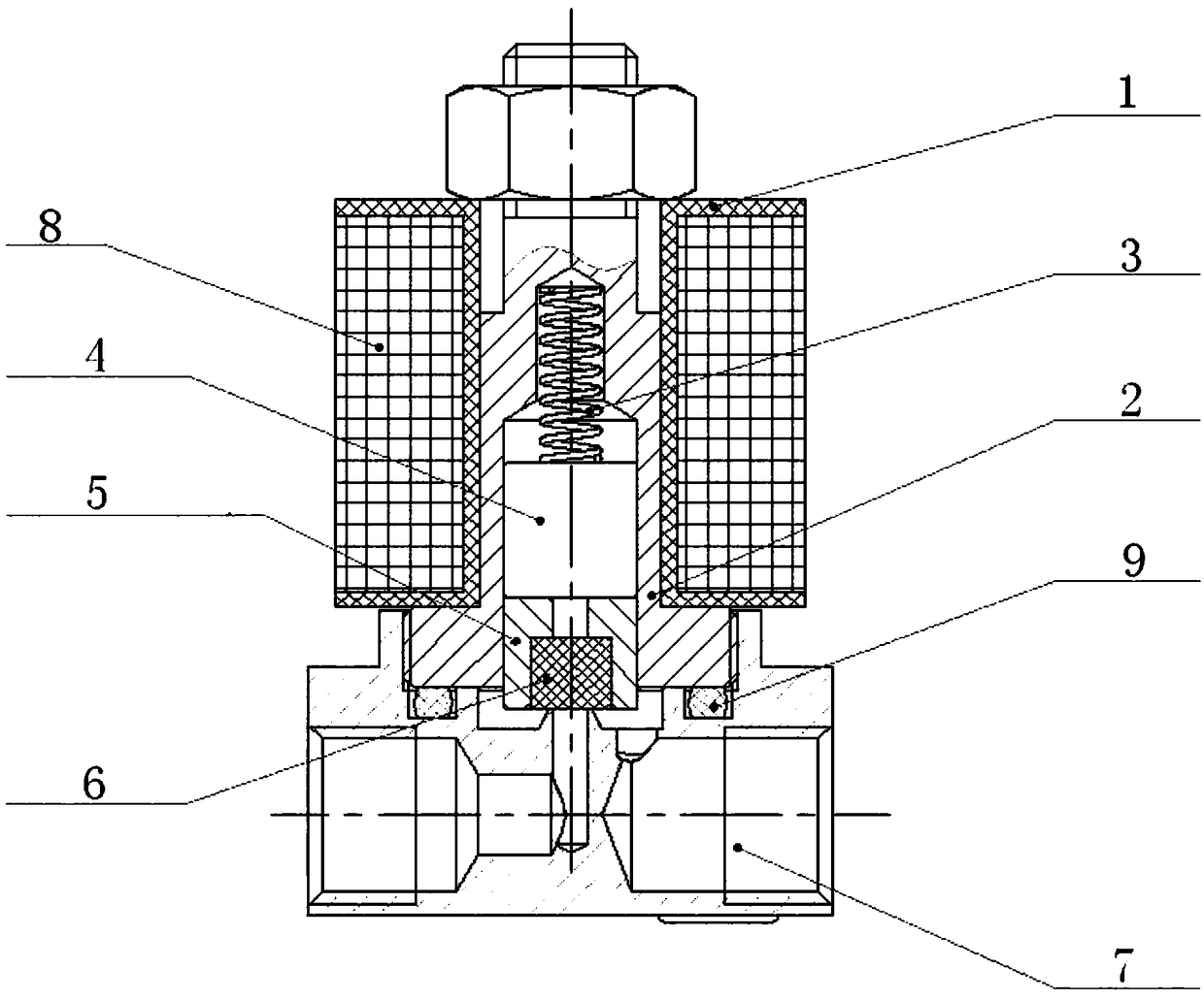
[0017] The present invention provides an electronically controlled flow valve, comprising: a coil frame 1, a non-magnetic guide 2, a spring 3, a permanent magnet 4, a connector 5, a rubber pad 6 and a valve body 7, wherein the coil frame 1 includes a cylinder Shaped main body, annular upper edge and annular lower edge, wherein the annular upper edge and annular lower edge are respectively connected to the top and bottom of the main body, an annular groove is formed between the main body and the annular upper edge and the annular lower edge, and in the annular groove The coil 8 is wound, the non-magnetic guide 2 is fixed on the inner side of the coil frame 1 and a guide hole is arranged inside it along its axial direction, and the spring 3, the permanent magnet 4 and the connecting member 5 are connected in sequence and are al...


PUM


Abstract

The invention discloses an electric control flow valve. The electric control flow valve comprises a coil framework, a non-magnetic guide part, a spring, a permanent magnet, a connecting piece, a rubber gasket and a valve body, wherein a coil is wound around the periphery of the coil framework, the non-magnetic guide part is fixedly arranged on the inner side of the coil framework, a guide hole isaxially formed in the non-magnetic guide part in the axial direction, the spring, the permanent magnet and the connecting piece are connected in sequence and are all arranged in the guide hole, the rubber pad is embedded into the bottom of the connecting piece, one end of the spring is fixedly connected to the top end of the guide hole, the permanent magnet is arranged in an area in which the electromagnetic force borne by the permanent magnet is in direct proportion to the current passing through the coil, the permanent magnet can drive the connecting piece and the rubber gasket to move up and down in the guide hole under the action of electromagnetic force and spring force, the valve body is fixedly connected to the lower part of the non-magnetic guide part, and the up-and-down movementof the rubber pad can be used for opening / blocking the connecting port of a fluid pipeline on the valve body and adjusting the size of the opening of the connecting port. The electric control flow valve is reasonable in structure, and the flow of the fluid can be adjusted by changing the size of the current passing through the coil.

Description

technical field [0001] The invention relates to the technical field of flow valves, and in particular provides an electronically controlled flow valve. Background technique [0002] For the control of fluid flow, proportional valves or stepping motors are generally used to control the valve opening or multi-channel parallel connection. The above methods are complicated and costly to implement. [0003] Therefore, developing a new type of electronically controlled flow valve to facilitate the control of fluid flow has become an urgent problem to be solved. Contents of the invention [0004] In view of this, the object of the present invention is to provide an electronically controlled flow valve to solve the problems of the existing flow valve such as complicated structure and inconvenient fluid flow control. [0005] The technical solution provided by the present invention is: an electronically controlled flow valve, including: a coil frame, a non-magnetic guide, a spring...

Claims


Application Information

Patent Timeline
Patent Type & Authority Applications(China)
IPC IPC(8): F16K31/06F16K27/02
CPCF16K27/029F16K31/0624
Inventor 王红军
Owner 王红军
Why Eureka
Eureka Blog
Learn More