Phase changing heat storing peak valley heating system and heating method thereof

A phase-change heat storage and heating system technology, which is applied in electric heating systems, heating systems, heating methods, etc., can solve the problems of phase-change heat storage and electricity peak shaving and valley filling, and achieve reduced operating costs, accurate heating efficiency, and energy saving The effect of power resources

Pending Publication Date: 2018-12-07
浙江泰昌新能源有限公司
View PDF8 Cites 8 Cited by
  • Summary
  • Abstract
  • Description
  • Claims
  • Application Information

AI Technical Summary

Problems solved by technology

[0007] In order to solve the technical problem to be solved by the present invention is to provide a phase-change heat storage peak-valley heating system and method in view of the above-mentioned problems, which mainly solve the problem of non-centralized heating in winter in northern rural areas, and phase-change heat storage power peak-shaving filling. The problem of intelligent and precise control of valley and electric heating power

Method used


Image

  • Phase changing heat storing peak valley heating system and heating method thereof
  • Phase changing heat storing peak valley heating system and heating method thereof
  • Phase changing heat storing peak valley heating system and heating method thereof

Examples


Embodiment 1

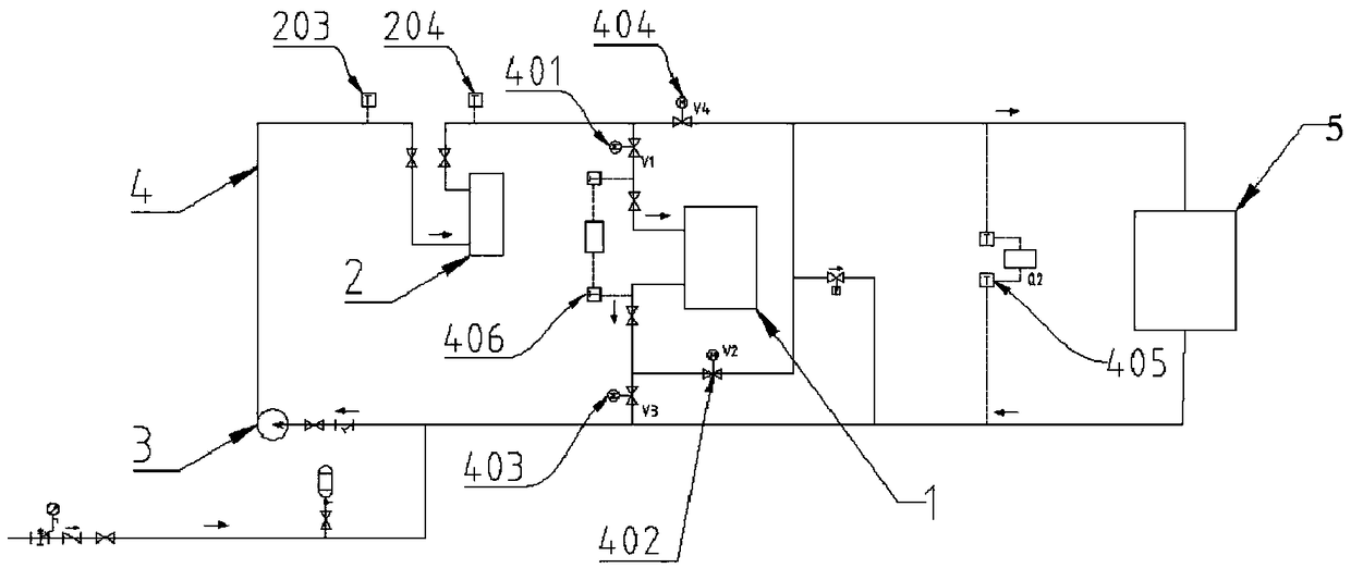
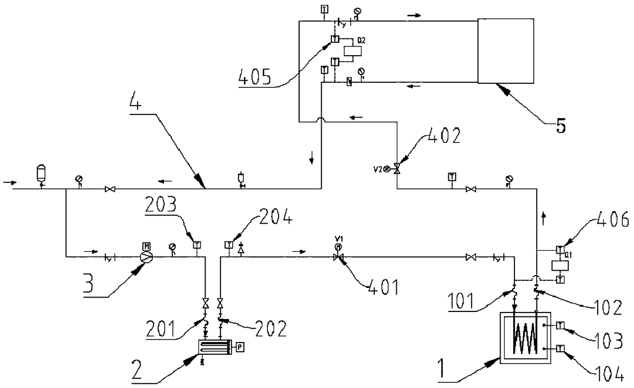
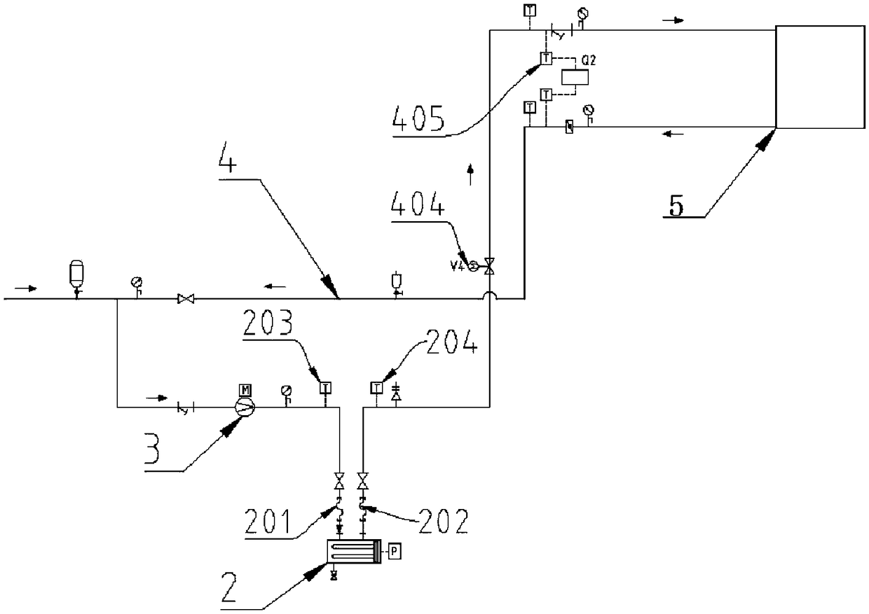
[0042] Embodiment 1: as figure 1 As shown, a phase change heat storage peak and valley heating system and method in this embodiment has a phase change heat storage device 1, an electric heating pipe 2, a circulating water pump 3, a circulating water network pipeline 4 and a heating control system. The thermal device 1 is provided with a heat storage water inlet 101 connected to the heating water outlet 202 of the electric heating tube 2, the heat storage water outlet 102 is connected to the user port 5, and the heating water inlet 201 of the electric heating tube 2 is connected to the circulating water pump 3, The circulating water network pipeline 4 is respectively provided with the electric V1 switch valve 401 of the heating water outlet 202 and the heat storage water inlet 101, the electric V2 switch valve 402 of the heat storage water outlet 102 and the user port 5, the heat storage water outlet 102 and the circulating water pump 3 electric V3 switch valve 403, heating wat...

Embodiment 2

[0067] The heating control system 6 dynamically controls the power output of the electric heating tube 2 according to the calorific value in the phase change heat storage device 1 . The existing heating system supplies heat directly from electric heating, and does not monitor the end in real time. The ultimate goal of this embodiment is to combine the temperature of the end to directly affect the temperature provided by the heating system, through the Q2 ultrasonic heat set at the user port 5 Meter 405 feeds back the user's temperature, and controls the real-time power of the electric heater 2 through comprehensive calculation.

[0068] The power regulator can control the real-time power percentage of the electric heating tube through the analog output current 4-20mA signal, that is, through the power percentage adjustment, the power control of the electric heating tube can be realized, and the stable operation of the system can be realized. In the calculation process, the main...


PUM


Abstract

The invention provides a phase changing heat storing peak valley heating system and method. The phase changing heat storing peak valley heating system is provided with a phase changing heat storing device, an electric heating pipe, a circulating water pump, a circulating water network pipeline and a heating control system; the phase changing heat storing device comprises a medium and low temperature phase changing material installed in a cabinet and a heat preserving shell; the electric heating pipe is controlled by the heating control system to be started at the time of valley electricity atnight, and heat is stored for the phase changing heat storing device; according to the value of heat in the phase changing heat storing device, the power output of the electric heating pipe is dynamically controlled, and the electric heating pipe stops at the moment of peak electricity; and through the circulating water network pipeline, heat is released from the interior of the phase changing heat storing device to heating of a user port, and the problems of non-concentrated type heating for rural areas in the north in winter, phase changing heat storing electric power peak-load shifting, andintelligent and accurate control over the electric heating power are solved.

Description

technical field [0001] The invention relates to the technical field of electric heating heat storage heating, in particular to a phase change heat storage peak-valley heating system and a heating method thereof. Background technique [0002] Phase change heat storage heating is mainly realized by using phase change materials. During the phase change heat storage process, the heat generated by electric heating is stored through heat storage elements. Usually, only 6-8 hours of electricity is used to store heat every day. During the peak electricity price period, the heat storage element releases the stored heat for heating. Therefore, phase change heat storage heating is widely used in the fields of power peak shaving and valley filling, waste heat utilization, and new energy development. It can realize peak electricity price periods throughout the day. Heating has achieved the advantages of energy saving and consumption reduction. [0003] Medium and low temperature phase c...

Claims


Application Information

Patent Timeline
Patent Type & Authority Applications(China)
IPC IPC(8): F24D13/04F24D19/10
CPCF24D13/04F24D19/1096F24D2200/08
Inventor 童敏孙爱东张鹏飞胡宝建梁忠
Owner 浙江泰昌新能源有限公司
Why Eureka
Try Eureka