
Waste heat recovery energy-saving drying oven and waste heat recovery method thereof

A waste heat recovery and oven technology, applied in drying, dryer, heating device and other directions, can solve the problems of poor drying effect, consume more heat, affect heat utilization rate, etc., to reduce energy consumption and improve drying. Drying efficiency, complete heat recovery effect

Active Publication Date: 2018-12-07
JUSHI GRP CO
View PDF5 Cites 3 Cited by
  • Summary
  • Abstract
  • Description
  • Claims
  • Application Information

AI Technical Summary

Problems solved by technology

Because the hot air is mixed with the cold air in the hot air supply pipe at the top of the drying chamber before entering the drying chamber, a large amount of heat will be dissipated to the outside air through the top plate of the furnace body, which will affect the heat utilization of the drying furnace rate, the drying effect is poor
At the same time, due to the narrow space of the cavity of the existing tunnel-type drying furnace, the hot air cannot flow well in the cavity of the drying furnace after the hot air is introduced, and it takes a lot of heat and time to finish drying the glass fiber. The drying also further affects the heat utilization rate and drying efficiency, which is not conducive to the actual development of industrial production

Method used


Image

  • Waste heat recovery energy-saving drying oven and waste heat recovery method thereof
  • Waste heat recovery energy-saving drying oven and waste heat recovery method thereof
  • Waste heat recovery energy-saving drying oven and waste heat recovery method thereof

Examples


Embodiment Construction

[0018] The following will clearly and completely describe the technical solutions in the embodiments of the present invention with reference to the accompanying drawings in the embodiments of the present invention. Obviously, the described embodiments are only some, not all, embodiments of the present invention. Based on the embodiments of the present invention, all other embodiments obtained by persons of ordinary skill in the art without making creative efforts belong to the protection scope of the present invention.

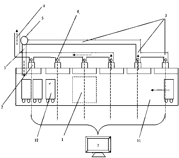
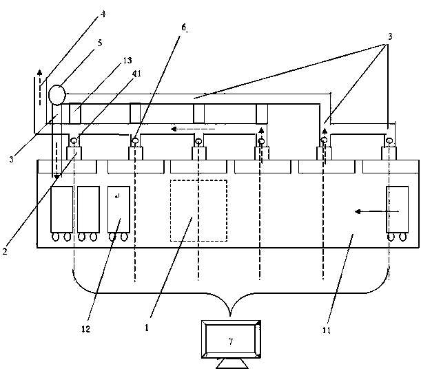
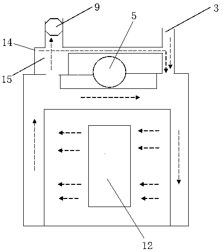
[0019] figure 1 , figure 2 Shows a schematic structural view of an embodiment of an energy-saving oven for waste heat recovery and utilization in the present invention, including: a furnace body (overall structure), a hot air supply system 15, a hot air supply pipeline 11, a dehumidifier 5, and a return unit connected to the dehumidifier 5 With the pipeline 3, the dehumidifying air pipeline 4, the temperature and humidity detector 6, the automatic adjustment...


PUM


Abstract

The invention relates to a waste heat recovery energy-saving drying oven and a waste heat recovery method thereof. The waste heat recovery energy-saving drying oven comprises a furnace body, a hot airsupply pipeline, a dehumidifying fan, recycling pipelines, dehumidifying air pipelines, temperature and humidity detectors, an automatic regulating valve, drying oven waste heat recovery and utilization systems and a server. The waste heat recovery energy-saving drying oven is characterized in that the furnace body is provided with an air supplementing inlet and the temperature and humidity detectors, the hot air supply pipeline communicates with the furnace body, the furnace body is internally provided with a plurality of drying cavities communicating mutually, and the upper portion of eachdrying cavity is provided with the corresponding dehumidifying air pipeline or the corresponding recycling pipeline; the dehumidifying fan is provided with a recycling opening and an exhaust outlet, and the recycling pipelines and the dehumidifying air pipelines communicate with the recycling opening and the exhaust outlet of the dehumidifying fan correspondingly; the drying oven waste heat recovery and utilization systems are mounted in the dehumidifying air pipelines and the recycling pipelines; and the adjusting regulating valve is mounted at the exhaust outlet of the dehumidifying fan, theair supplementing inlet communicates with the recycling pipelines, and the server is connected with the temperature and humidity detectors, the automatic regulating valve and a hot air supply system.Compared with the prior art, the waste heat recovery energy-saving drying oven and the waste heat recovery method thereof have the characteristics of concise and reasonable structure, convenient use,high energy utilization rate, low cost and the like.

Description

technical field [0001] The application relates to the technical field of oven and waste heat utilization, in particular, to an energy-saving oven for waste heat recovery and a method for recovery of waste heat. Background technique [0002] Glass fiber is an inorganic non-metallic material with excellent performance. It is made of glass balls or waste glass through high-temperature melting, wire drawing, baking, winding and other processes. Glass fiber has the advantages of good insulation, high heat resistance, and corrosion resistance, and is widely used in various fields. [0003] Some sizing agent emulsions are used in the process of making glass fibers. In order to solidify the sizing agent into a film and remove excess water in the drawn glass fibers, it is necessary to dry the drawn glass fibers. The existing one used for drying glass fibers is a single-layer tunnel-type drying furnace. A drying cavity is built into the furnace body of the drying furnace. The yarn c...

Claims


Application Information

Patent Timeline
Patent Type & Authority Applications(China)
IPC IPC(8): F26B9/06F26B21/00F26B21/08F26B25/00F26B21/10F26B23/00
CPCF26B9/06F26B21/00F26B21/08F26B21/10F26B23/002F26B25/00Y02P70/10
Inventor 俞卫国陆鑫忠朱张辉施晓钢王大平
Owner JUSHI GRP CO
Learn More