Multifunctional experimental device for Lenz's law

An experimental device, the technology of Lenz's law, applied in the field of physical science experimental devices, can solve the problems such as the inability to intuitively demonstrate the opposite magnetic field of the solenoid, the single form of the demonstration device, unfavorable learning and understanding of Lenz's law, etc., so as to deepen the understanding. and understanding, the experimental results are intuitive, and the use of flexible effects

Inactive Publication Date: 2018-12-07
SHAANXI NORMAL UNIV
View PDF9 Cites 1 Cited by
  • Summary
  • Abstract
  • Description
  • Claims
  • Application Information

AI Technical Summary

Problems solved by technology

[0006] In order to solve the technical problem that the Lenz's law demonstration device in the prior art has a single form and cannot intuitively demonstrate the opposite magnetic field generated

Method used


Image

  • Multifunctional experimental device for Lenz's law
  • Multifunctional experimental device for Lenz's law

Examples


Embodiment 1

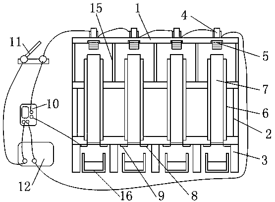
[0032] In order to solve the technical problem of the single form of Lenz's law demonstration device in the prior art, this embodiment provides a multifunctional Lenz's law experimental device, such as figure 1 As shown, it includes the first bracket 1, the second bracket 2 and the third bracket 3 stacked in sequence from top to bottom, the first bracket 1 and the second bracket 2 are detachably connected, the second bracket 2 and the third bracket 3 The first support 1, the second support 2, and the third support 3 are all made of non-magnetic, non-conductive, high-transparency plexiglass material, and the top surface of the top wall of the first support 1 is provided with four copper Coil 4, the bottom surface of the top wall of the first support 1 is provided with four grooves for placing the magnet 5, the top wall of the second support 2 is provided with four round holes for the solenoid to pass through, and the top wall of the third support 3 The wall is provided with fou...

Embodiment 2

[0042] The difference from the above-mentioned embodiment is that this embodiment uses an enameled wire with a diameter of 1.5 mm to uniformly wind 300, 900, 1500, and 2100 turns of the solenoid on the plexiglass tube, and selects 4 groups with the same thickness and diameter. The cylindrical magnet 5 is made to be adsorbed in the grooves on the lower side of 4 groups of copper coils 4, the constant current source 12 switch is turned off, and the speed at which the magnet 5 falls is observed, and the time taken by the 4 groups of magnets 5 to fall can be checked by the timer 10. The influence of the number of turns of the solenoid on the hindering effect of the magnet 5 is compared under the same wire diameter.

Embodiment 3

[0044] The difference from the above-mentioned embodiment is that this embodiment adopts two solenoids, which are respectively 2.0 mm in diameter enameled wire and 1500 turns uniformly wound on the plexiglass tube, and a width of 2.0 mm and a thickness of A second-generation high-temperature superconducting tape with a diameter of 0.1 mm is evenly wound on a solenoid with 1500 turns on a polytetrafluoroethylene tube. The high-temperature superconducting tape outside the polytetrafluoroethylene tube needs to be packaged in a low-temperature container; two groups are selected Cylindrical magnets 5 with the same thickness and diameter are adsorbed in the grooves on the lower side of the two sets of copper coils 4, the constant current source 12 switch is turned off, and the falling speed of the magnets 5 is observed, and the two sets of magnets 5 are checked by the timer 10. The falling time can be used to compare the influence of the solenoid and the polytetrafluoroethylene tube ...


PUM


Abstract

The invention relates to a multifunctional experimental device for Lenz's law, comprising a first bracket, a second bracket and a third bracket stacked in sequence from top to bottom. The first bracket and the second bracket are detachably connected, and the second bracket and the third bracket are fixedly connected. Multiple copper coils are arranged on the top surface of the top wall of the first bracket, and multiple grooves used to place magnets are arranged on the bottom surface of the top wall of the first bracket. Multiple circular holes for solenoids to pass through are arranged in thetop wall of the second bracket. Multiple step holes used to support the bottom ends of the solenoids are arranged in the top wall of the third bracket. The copper coils, the grooves, the circular holes and the step holes correspond in number and position. Each solenoid consists of an outer tube and an inner tube, and the outer tube sleeves the inner tube. Through the detachable connection betweenthe first bracket and the second bracket of the experimental device, the solenoids can be replaced conveniently, and the experimental device is more flexible and changeable in use.

Description

technical field [0001] The invention belongs to the technical field of physical science experiment devices, and in particular relates to a multifunctional Lenz law experiment device. Background technique [0002] Lenz's law is an important law in the field of electromagnetism. It can be used to judge the direction of electromotive force generated by electromagnetic induction. It was discovered by Russian physicist Heinrich Lenz in 1834. It can be expressed as: the induced current has such a direction that the magnetic field of the induced current always hinders the change of the magnetic flux that causes the induced current. It can also be stated that the effect of the induced current always opposes the cause of the induced current. The macroscopic manifestation is the electromagnetic damping phenomenon: when the closed conductor and the magnetic pole move relative to each other, electromagnetic resistance will be generated between the two to hinder the relative movement. ...

Claims


Application Information

Patent Timeline
IPC IPC(8): G09B23/18
CPCG09B23/181
Inventor 杨万民杨芃焘
Owner SHAANXI NORMAL UNIV
Why Eureka
Try Eureka