
Double layer standard squirrel cage conductor rotor high torque density permanent magnet governor

A permanent magnet speed governor, conductor rotor technology, applied in the direction of permanent magnet clutches/brakes, electromechanical devices, electrical components, etc., can solve the problem of increasing the axial length of the device, weakening the air gap magnetic field strength, increasing the magnetic circuit reluctance problem, to reduce the axial length and solve the effect of local overheating

Active Publication Date: 2019-10-11
SOUTHEAST UNIV
View PDF9 Cites 2 Cited by
  • Summary
  • Abstract
  • Description
  • Claims
  • Application Information

AI Technical Summary

Problems solved by technology

As a result, the structure of the electric actuator is complex, the mechanical strength is high, and the space occupied in the axial direction is relatively large.
The existing permanent magnet governor realizes the speed regulation function of the device by changing the axial relative position of the permanent magnet rotor and the conductor rotor, and increases the axial length of the device. It is used as a device installed between the prime mover and the pump and fan load. It is a product for industrial transformation of speed regulation and energy saving, which has certain space limitations
In addition, the traditional permanent magnet eddy current governor usually adopts a single permanent magnet rotor and a single conductor rotor, and the conductor part of the conductor rotor of the traditional permanent magnet eddy current governor is usually composed of a uniform thickness of copper layer fixed on the surface of the conductor rotor core. The magnetic permeability of the conductor part is close to that of air, which increases the reluctance of the magnetic circuit, causes the air gap magnetic field to weaken, and reduces the torque density of the permanent magnet governor to a certain extent.

Method used


Image

  • Double layer standard squirrel cage conductor rotor high torque density permanent magnet governor
  • Double layer standard squirrel cage conductor rotor high torque density permanent magnet governor
  • Double layer standard squirrel cage conductor rotor high torque density permanent magnet governor

Examples


Embodiment 1

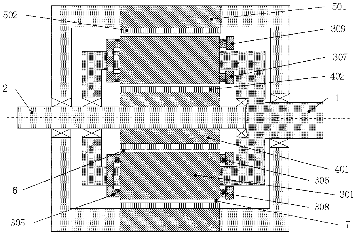
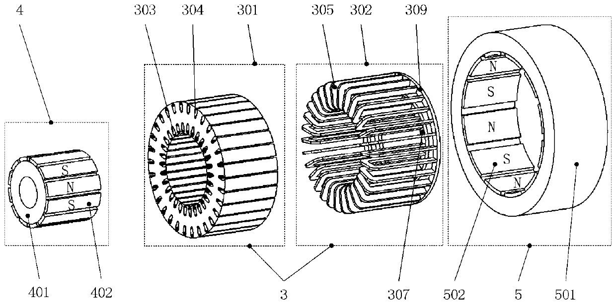
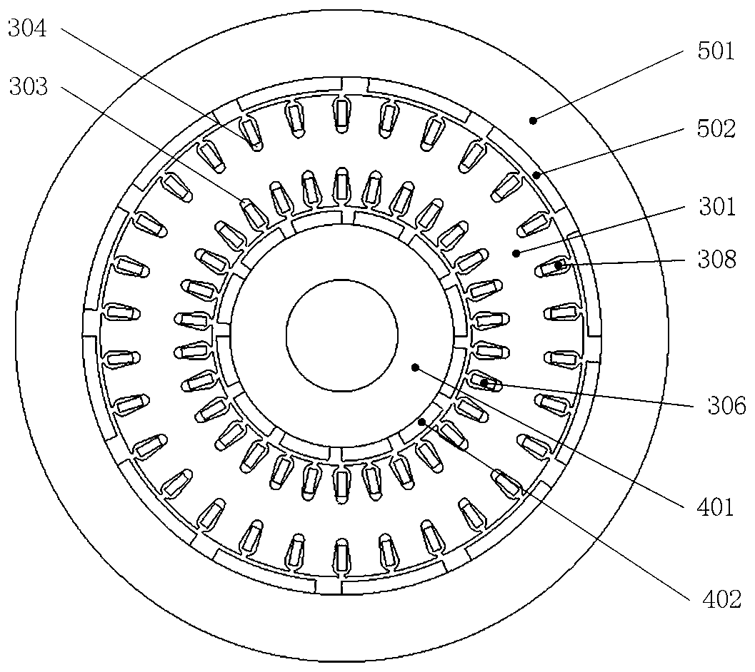
[0031] Such as figure 1 with figure 2 As shown, the present invention discloses a double-layer standard squirrel-cage conductor rotor high torque density permanent magnet speed governor, which includes an input shaft 1 and an output shaft 2 arranged on the same central axis, and a gap between the input shaft 1 and the output shaft 2 Fixed connection with bearings. In the present invention, the input shaft 1 includes a central uniaxial body and a cylindrical shaft body for passing the conductor rotor 3 . In the present invention, the first permanent magnet rotor 4 and the second permanent magnet rotor 5 pass through the output shaft 2 and provide torque for the first permanent magnet rotor 4 and the second permanent magnet rotor 5 . The present invention also includes a bracket 8 for passing through the second permanent magnet rotor 5 , one end of the bracket 8 is connected to the output shaft 2 through a bearing, and the other end is also connected to the input shaft 1 thro...

Embodiment 2

[0036] Such as Image 6 with Figure 7 As shown, the present invention discloses a double-layer standard squirrel-cage conductor rotor high torque density permanent magnet speed governor, which includes an input shaft 1 and an output shaft 2 arranged on the same central axis, and a gap between the input shaft 1 and the output shaft 2 Fixed connection with bearings. In the present invention, the input shaft 1 includes a central thin uniaxial body and a disk-shaped shaft body for passing the conductor rotor 3 . In the present invention, the first permanent magnet rotor 4 and the second permanent magnet rotor 5 pass through the output shaft 2 and provide torque for the first permanent magnet rotor 4 and the second permanent magnet rotor 5 . The output shaft 2 of the present invention is erected with a bracket 8 for passing through the second permanent magnet rotor 5 , one end of the bracket 8 is connected with the output shaft 2 through a bearing, and the other end is also conn...


PUM


Abstract

The invention discloses a double-layer standard squirrel cage conductor rotor high torque density permanent magnetic speed controller. The permanent magnetic speed controller comprises an input shaftand an output shaft set on the same central axis, wherein the input shaft is provided with a conductor rotor in a penetration mode, the output shaft is provided with a first permanent magnet rotor anda second permanent magnet rotor in a penetration mode, the first permanent magnet rotor and the second permanent magnet rotor can rotate with relative concentricity, the first permanent magnet rotor,the conductor rotor and the second permanent magnet rotor are sequentially concentrically sleeved in the radial direction, a first air gap is between the first permanent magnet rotor and the conductor rotor, and a second air gap is between the conductor rotor and the second permanent magnet rotor. The permanent magnetic speed controller is advantaged in that through rotation of the first permanent magnet rotor or the second permanent magnet rotor, the relative rotation angle between the first permanent magnet rotor and the second permanent magnet rotor is changed, the speed control function of the speed controller is achieved, in the speed control process, overcoming the cogging torque is only required, the function of the speed controller is different from the speed control function achieved through adjusting an axial air gap between a magnetic rotor and a conductor rotor in the prior art, and axial length of the permanent magnetic speed controller is effectively reduced.

Description

technical field [0001] The invention relates to a permanent magnet governor, in particular to a double-layer standard squirrel cage conductor rotor high torque density permanent magnet governor. Background technique [0002] With the promotion and application of high-performance permanent magnet materials, the permanent magnet speed control technology, which has developed rapidly, is a new type of speed control and energy-saving technology for motor drive systems applied between the prime mover and the load. The speed-regulating permanent magnet coupler has a good energy-saving effect, reduces operating costs, and can also realize the soft start and soft stop functions of the motor. It can operate in harsh environments such as flammable, explosive, humid, and high dust content, and it is a mechanical structure that can adapt to situations such as unstable power grid quality and impact loads caused by current changes. Mainly used in the chemical industry, petrochemical indus...

Claims


Application Information

Patent Timeline
Patent Type & Authority Patents(China)
IPC IPC(8): H02K16/00H02K49/10
Inventor 林鹤云李毅搏陶前程阳辉王海涛
Owner SOUTHEAST UNIV
Learn More