Electrical automatic protection switch

An automatic protection and switching technology, applied in the electrical field, can solve problems such as failures and achieve high sensitivity

Pending Publication Date: 2018-12-07
浙江机电职业技术学院
View PDF1 Cites 1 Cited by
  • Summary
  • Abstract
  • Description
  • Claims
  • Application Information

AI Technical Summary

Problems solved by technology

In the prior art, when electrical equipment is running, it is inevitable that failures will occur. Therefore, in order to avoid deterioration of failures, a protector is needed

Method used


Image

  • Electrical automatic protection switch

Examples


Embodiment Construction

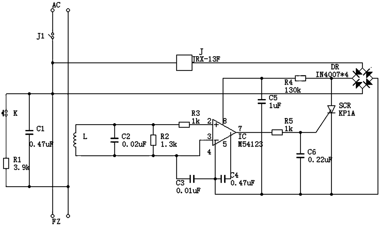
[0009] The present invention will be further described below in conjunction with accompanying drawing:

[0010] Such as figure 1 Shown: the present invention includes first resistor R1 to fifth resistor R5, first capacitor C1 to sixth capacitor C6, switch K, inductor L, relay J, amplifier IC, thyristor SCR and rectifier DR, first resistor R1 The first terminal of the switch K is connected to the first terminal of the first resistor R1, and the second terminal of the first resistor R1 is simultaneously connected to the first terminal of the first capacitor C1 and one terminal of the AC power supply AC, and the second terminal of the switch K is simultaneously connected to the first terminal of the first capacitor C1 The second terminal of the AC power supply AC, the first terminal of the relay J is connected to the first input terminal of the rectifier DR, the second terminal of the relay J is connected to the second input terminal of the rectifier DR, and the normally open ter...


PUM


Abstract

The invention discloses an electric automatic protection switch, which comprises a first resistor to a fifth resistor, a first capacitor to a sixth capacitor, a switch, an inductor, a relay, an amplifier, a silicon controlled rectifier and a rectifier. The electrical automatic protection switch induces a current signal in an alternating current circuit through the inductor, amplifies the induced signal through the amplifier and triggers control according to the signal, thereby being high in sensitivity, being capable of timely disconnecting a power supply when electrical equipment has a fault,and having popularization and application values.

Description

technical field [0001] The invention relates to the field of electrical technology, in particular to an electrical automatic protection switch. Background technique [0002] Electricity is a general term for disciplines or engineering fields such as the production, transmission, distribution, use, and electrical equipment manufacturing of electric energy. It is a science to create, maintain and improve limited space and environment by means of electrical energy, electrical equipment and electrical technology, covering three aspects of electrical energy conversion, utilization and research, including basic theory, applied technology, facilities and equipment, etc. In the prior art, when electrical equipment is running, faults and the like will inevitably occur. Therefore, in order to avoid deterioration of faults, a protector is needed. Contents of the invention [0003] The object of the present invention is to provide an electric automatic protection switch in order to s...

Claims


Application Information

Patent Timeline
Patent Type & Authority Applications(China)
IPC IPC(8): H03K17/04H03K17/51
CPCH03K17/04H03K17/51H03K2017/515
Inventor 钱炳芸朱克捷
Owner 浙江机电职业技术学院
Why Eureka
Try Eureka