
Power control circuit and method of electromagnetic heating device

An electromagnetic heating device and power control technology, which is applied in the direction of electric heating device, induction heating control, electric/magnetic/electromagnetic heating, etc., can solve the problems of reduced lifespan, high circuit cost, temperature rise, etc., and achieve good stability and circuit simple and reliable effect

Inactive Publication Date: 2018-12-07
JOYOUNG CO LTD
View PDF4 Cites 10 Cited by
  • Summary
  • Abstract
  • Description
  • Claims
  • Application Information

AI Technical Summary

Problems solved by technology

Electromagnetic heating cooking utensils need to use IGBT alternating on and off to achieve electromagnetic resonance. When heating with high power, the IGBT works well, but when heating with low power, the loss of IGBT increases, the temperature rises, and the service life decreases, making the cooking utensils job instability
For this reason, in order to achieve low-power electromagnetic heating, the industry usually adopts the following methods: 1. Realize by intermittent heating, that is, heating for a period of time and stopping heating for a period of time, so as to reduce the heat loss generated by the IGBT during low-power heating, but this The discontinuous heating of the first heating method makes the user experience poor; 2. Using the silicon controlled rectifier wave dropping method, by controlling the switching on and off of the silicon controlled rectifier, half a cycle of the original continuous cycle waveform is lost, but this method needs to be set The zero-crossing detection circuit performs zero-crossing detection, and the thyristor must be controlled to perform on-off actions in each waveform cycle, the circuit cost is high and the stability is not good

Method used


Image

  • Power control circuit and method of electromagnetic heating device
  • Power control circuit and method of electromagnetic heating device
  • Power control circuit and method of electromagnetic heating device

Examples


Embodiment Construction

[0027] The following will clearly and completely describe the technical solutions in the embodiments of the present invention with reference to the accompanying drawings in the embodiments of the present invention. Obviously, the described embodiments are only some, not all, embodiments of the present invention. Based on the embodiments of the present invention, all other embodiments obtained by persons of ordinary skill in the art without creative efforts fall within the protection scope of the present invention.

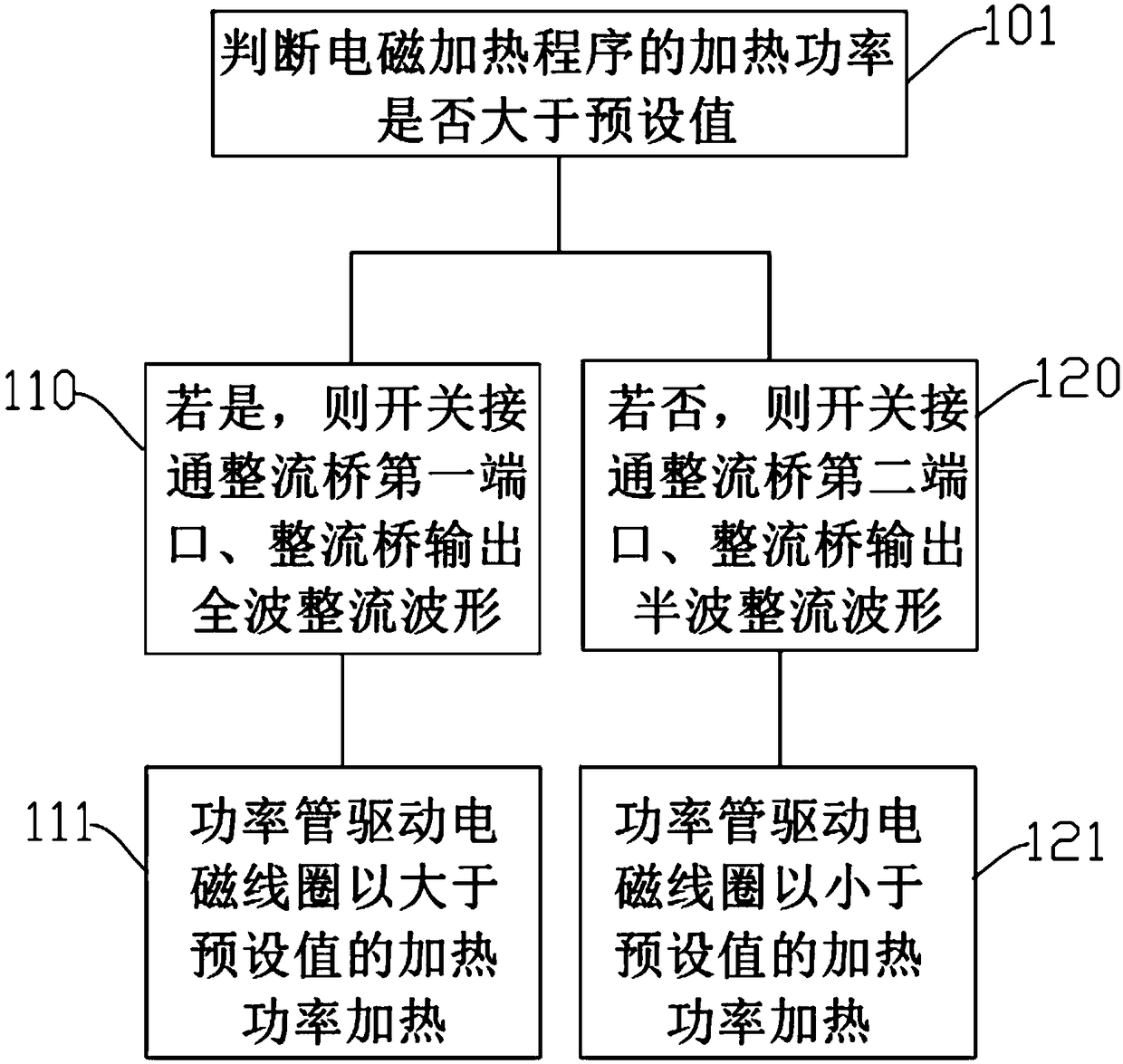
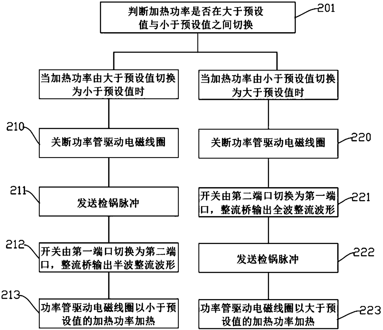
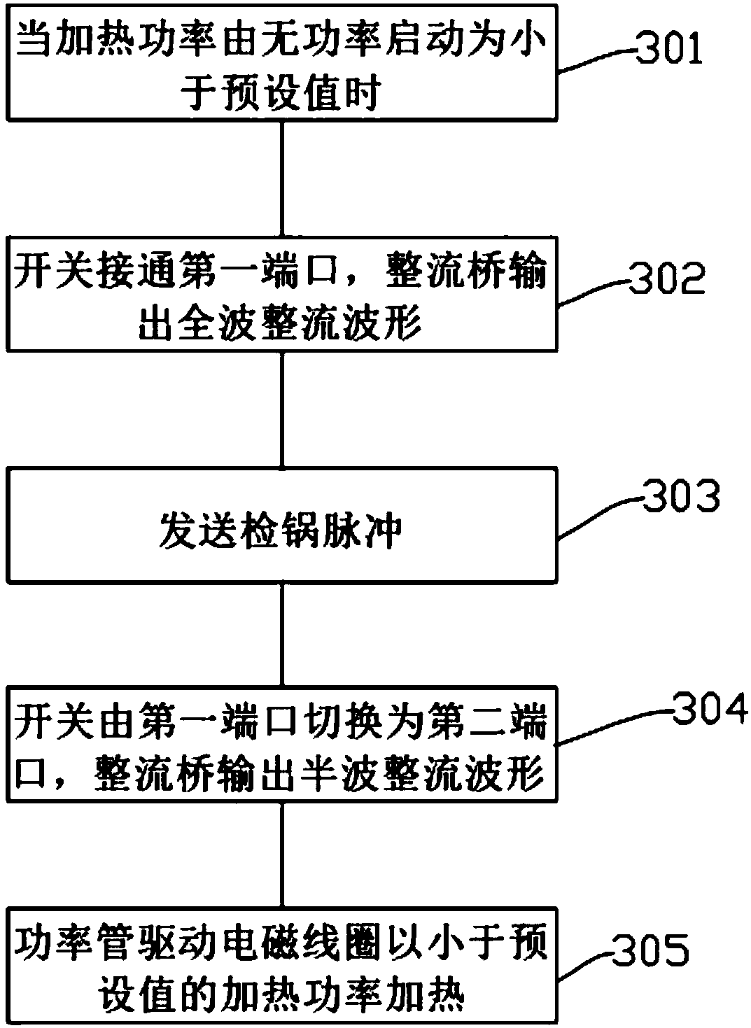
[0028] see Figure 1 to Figure 3 , the present invention provides a power control method of an electromagnetic heating device. The power control method includes the following steps: 101. Judging whether the heating power of the electromagnetic heating program is greater than a preset value; 110. When the heating power is greater than a preset value, then The switch turns on the first port of the rectifier bridge, and the rectifier bridge outputs a full-wave rectifi...


PUM


Abstract

The invention provides a power control circuit of an electromagnetic heating device. The power control circuit comprises a rectifier module, a control module, a power tube and a resonance module. Therectifier module comprises a rectifier bridge. The rectifier bridge has a first port and a second port. The power control circuit further includes a switch connected to the rectifier bridge. The switch switches between the first port and the second port under the control of the control module so that the rectifier bridge outputs a full-wave rectification waveform or a half-wave rectification waveform. The control module drives the power tube to control the resonance module to operate under the full-wave rectification waveform or the half-wave rectification waveform so as to output different heating powers. By means of the switch, the waveform output by the rectifier bridge can be a full-wave rectification waveform or a half-wave rectification waveform, thereby realizing switching between high-power heating and low-power heating. The power control circuit is realized by a hardware circuit, and is simple, reliable, and stable. The invention also provides a power control method of the electromagnetic heating device.

Description

technical field [0001] The invention relates to the technical field of kitchen appliances, in particular to a power control circuit and a power control method of an electromagnetic heating device. Background technique [0002] The heating principle of the electromagnetic heating device is that the electromagnetic heating device generates an alternating magnetic field, and the ferromagnetic material placed in the alternating magnetic field generates heat by itself due to induction. Electromagnetic heating is more common in cooking utensils, such as induction cooker, IH rice cooker, etc. Cooking utensils using electromagnetic heating are popular among users because of their high thermal efficiency, cleanliness, and convenience. Electromagnetic heating cooking utensils need to use IGBT alternating on and off to achieve electromagnetic resonance. When heating with high power, the IGBT works well, but when heating with low power, the loss of IGBT increases, the temperature rises,...

Claims


Application Information

Patent Timeline
IPC IPC(8): H05B6/06
CPCH05B6/06H05B6/062
Inventor 朱泽春胡炜张伟
Owner JOYOUNG CO LTD
Learn More