Light emission instructing device and light emitting system

A technology for indicating devices and light emitters, applied in electroluminescent light sources, lighting devices, light sources, etc., can solve problems such as unfavorable costs and achieve reliable control of performance effects

Inactive Publication Date: 2018-12-07
KUWAGATA CO LTD
View PDF2 Cites 0 Cited by
  • Summary
  • Abstract
  • Description
  • Claims
  • Application Information

AI Technical Summary

Problems solved by technology

Therefore, in the lighting system, since an operator for changing the lighting mode is required for each individual system, it is not cost-effective to require an operator and an operation console every time a small-scale event or the like is performed.

Method used


Image

  • Light emission instructing device and light emitting system
  • Light emission instructing device and light emitting system
  • Light emission instructing device and light emitting system

Examples


Embodiment Construction

[0042] Hereinafter, embodiments of the present invention will be described with reference to the accompanying drawings.

[0043] (an embodiment)

[0044]

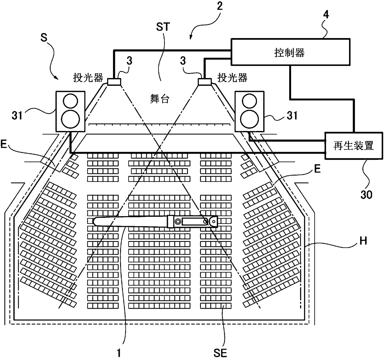
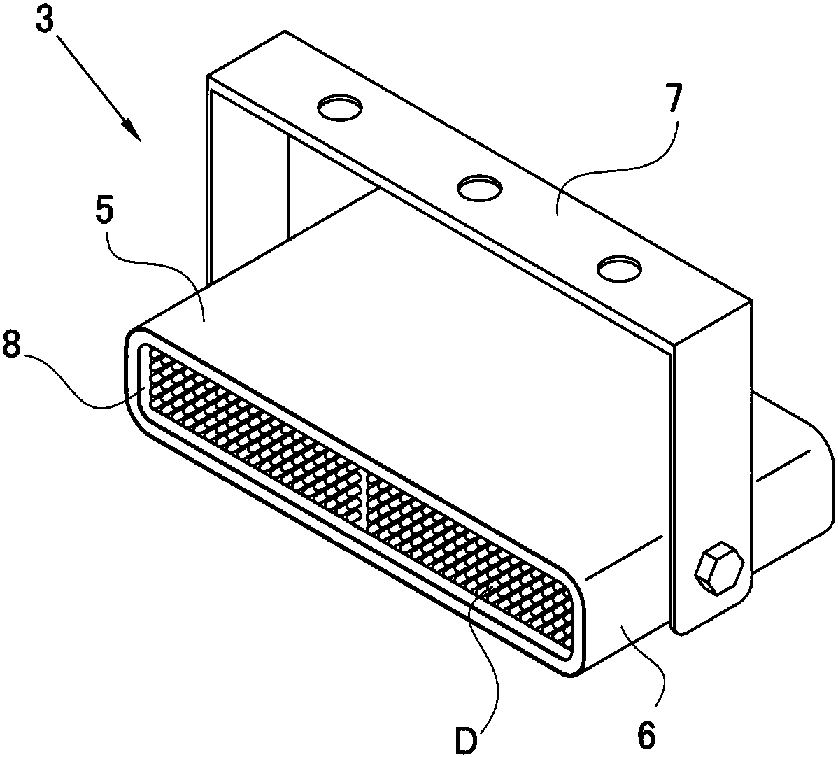
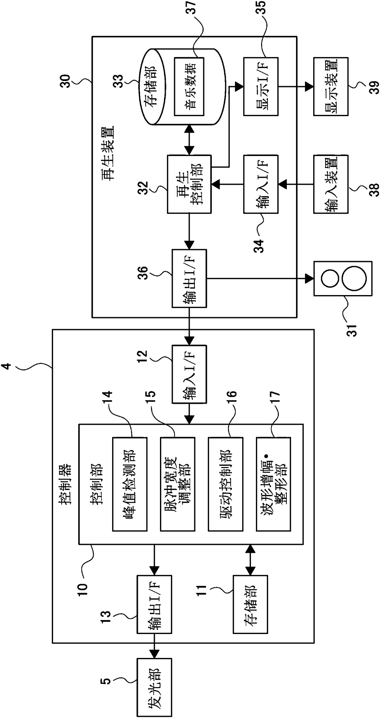
[0045] combined with Figure 1~4 The light-emitting indicating device of this embodiment will be described. figure 1 is a schematic diagram showing an outline of a light emitting system of an embodiment, figure 2 is a perspective view showing a light projector constituting a light-emitting indicating device according to an embodiment, image 3 is a block diagram showing a schematic configuration of a light emitting system according to an embodiment, Figure 4 It is a circuit diagram showing a schematic configuration of a light emitting pointing device according to an embodiment.

[0046] The light emitting system S of this embodiment includes a plurality of light emitters 1 described later and a light emission instructing device 2 for instructing light emission by outputting an infrared signal to the light emitters 1...


PUM


Abstract

The invention provides a light emission instructing device and a light emitting system, capable of automatically performing an effect manipulation and further capable of controlling an effect. A lightemission instruction device (2) for instructing light emission to the light emitter (1) by outputting an infrared signal to the light emitter (1) includes an input interface (12) for accepting an input of an audio signal, a peak detection unit (14) for detecting the peak position on a time shaft, and a drive control section (16) which takes the peak position detected by the peak detection unit (14) as a triggering condition to generate a control code including at least one of change instruction signals of color and pattern emitted by the light emitter (1) and output an infrared signal modulated by this control code.

Description

technical field [0001] The invention relates to a light-emitting indicating device and a light-emitting system that indicate light-emitting by outputting infrared signals toward a light-emitting device. Background technique [0002] It is known, for example, in a venue for an event or a concert, to output an infrared signal including a control code from a lighting indicating device for the audience to hold a light emitter, and to implement a predetermined pattern and color light emission on the light emitter receiving the infrared signal. system (for example, refer to Patent Document 1). In such a light emitting system, it has been disclosed that the sound input from the loudspeaker is divided into four for each frequency band for the purpose of improving the performance effect by the light emitting mode of the light emitter, and then analog / digital conversion is performed on the signal, and based on A digital signal for each frequency band creates a lighting processing com...

Claims


Application Information

Patent Timeline
Patent Type & Authority Applications(China)
IPC IPC(8): H05B33/08H05B37/02H05B44/00
CPCH05B45/20H05B47/12Y02B20/40
Inventor 山崎德明
Owner KUWAGATA CO LTD
Why Eureka
Try Eureka