Commutation torque ripple suppression method for permanent magnet brushless DC motor

A permanent magnet brushless DC and fluctuation suppression technology, applied in the direction of torque ripple control, etc., can solve the problems of increasing the complexity of the system and control strategy

Inactive Publication Date: 2011-08-24
TIANJIN UNIV
View PDF4 Cites 27 Cited by
  • Summary
  • Abstract
  • Description
  • Claims
  • Application Information

AI Technical Summary

Problems solved by technology

[0004] In the previous literature research, the current control strategy in the commutation process is mostly based on the PWM modulation strategy, and most of the current commutation torque fluctuation suppression strategies consider the high and low speed running states of the motor separately, which increases the complexity of the system and control strategy , so in practical applications, it is necessary to find a unified method that can effectively suppress commutation torque fluctuations in the entire speed range, improve the operating performance of permanent magnet brushless DC motors, and expand its application fields

Method used


Image

  • Commutation torque ripple suppression method for permanent magnet brushless DC motor
  • Commutation torque ripple suppression method for permanent magnet brushless DC motor
  • Commutation torque ripple suppression method for permanent magnet brushless DC motor

Examples


Embodiment Construction

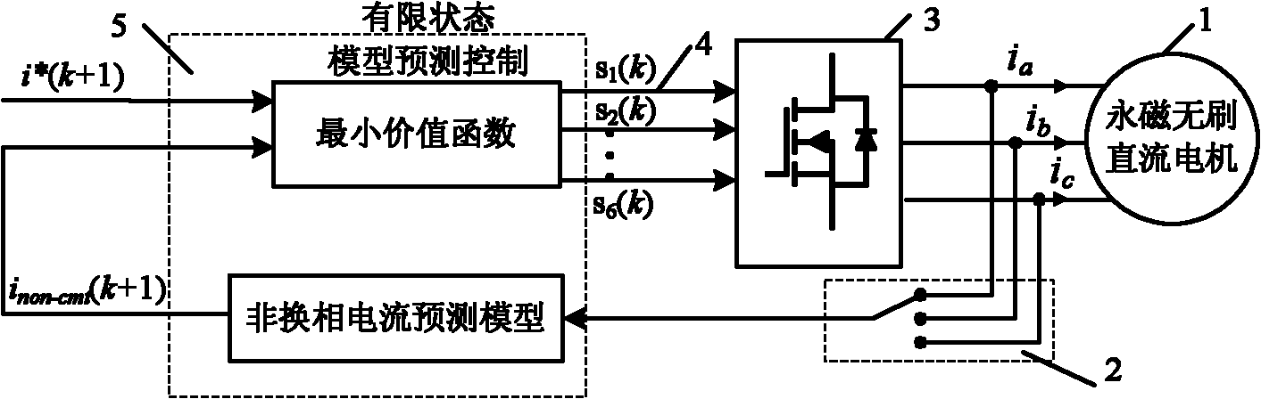
[0034] The method for suppressing the commutation torque fluctuation of the permanent magnet brushless DC motor proposed by the present invention can be applied to the permanent magnet brushless DC motor, and a typical permanent magnet brushless DC motor system such as figure 1 As shown, it includes a permanent magnet brushless DC motor (1), a current sensor (2), a three-phase full-bridge inverter circuit (3), a drive circuit (4) and a DSP controller (5).

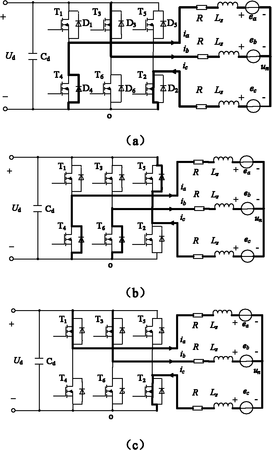
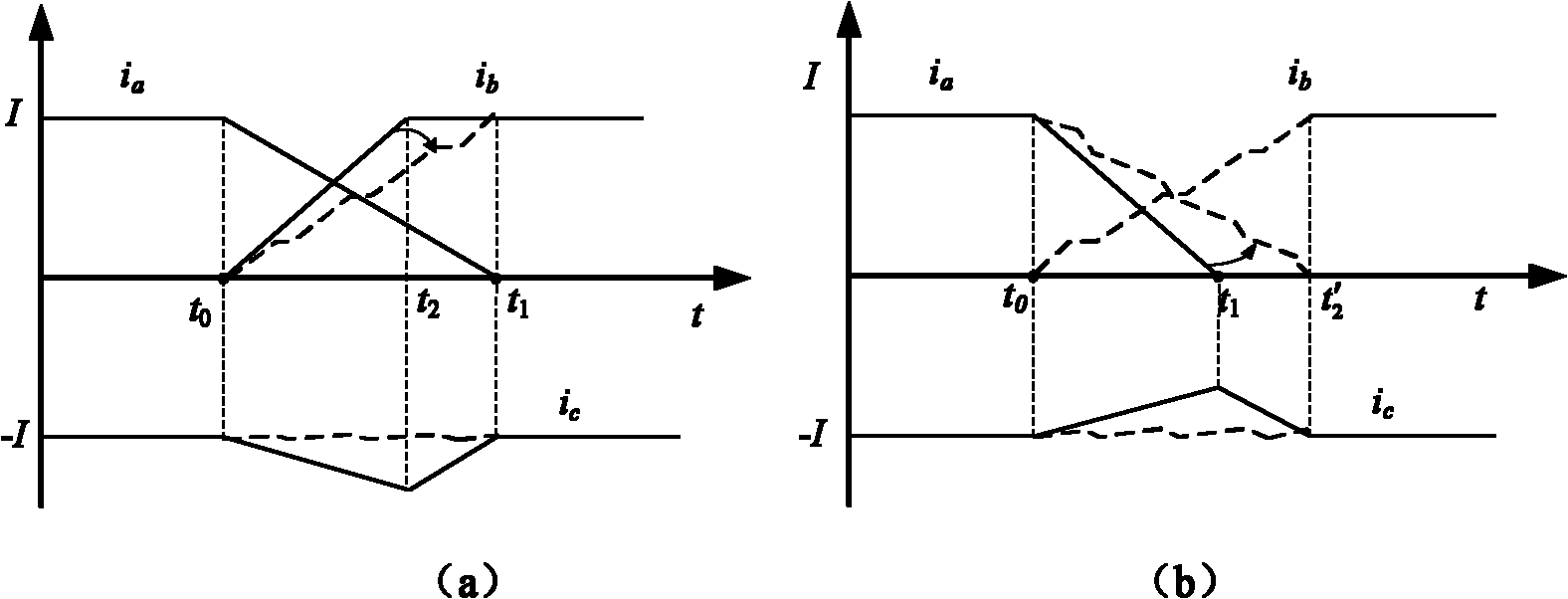
[0035] The three-phase full-bridge permanent magnet brushless DC motor operates with two-to-two conduction commutation at an electrical angle of 120°. During the commutation process, the off-phase current refers to the off-phase winding current; the on-phase current refers to the on-phase winding Current; non-commutation current refers to the winding current that does not participate in commutation. During the commutation process of the permanent magnet brushless DC motor, due to the mismatch between the falling slope of th...


PUM


Abstract

The invention belongs to the technical field of motor control, and relates to a commutation torque ripple suppression method for a permanent magnet brushless DC motor. The method comprises the following steps of: detecting a rising edge or falling edge of a Hall signal, starting commutation, and executing the commutation torque ripple suppression method; acquiring a non-commutation current sampling value and a motor running speed at a current moment; calculating back electromotive forces of phases of a three-phase winding at the next moment according to the motor running speed and a commutation mode respectively; obtaining the voltages to power earth of end points of the three-phase winding in different inverter circuit switching-on states at the next moment respectively; predicting predicted values of non-commutation current in the different inverter circuit switching-on states at the next moment respectively; performing estimation on the predicted values of the non-commutation current in the different inverter circuit switching-on states by utilizing a value function; selecting the inverter circuit switching-on state in which the value function has the smallest value as the inverter circuit switching-on state of the next moment, and generating a corresponding inverter circuit control signal; and detecting the current of a corresponding switched-off phase is reduced to zero, finishing the commutation process, and stopping the commutation torque ripple suppression method. By the method, the commutation process can be accurately determined, and control over the inverter circuit switching-on state can be realized relatively better at the moment of commutation to realize commutation torque ripple suppression.

Description

technical field [0001] The invention provides a method for suppressing commutation torque fluctuations of a permanent magnet brushless direct current motor, which belongs to the technical field of motor control, and in particular relates to the technical field of permanent magnet brushless direct current motor control. Background technique [0002] The permanent magnet brushless DC motor adopts electronic commutation, which eliminates the mechanical contact device composed of commutator and brush, so the maintenance cost is low and the service life is long; the excitation is obtained through the permanent magnet of the rotor, no excitation current is required, no excitation loss, and the efficiency is high. Higher; has a smaller moment of inertia, has a faster response under a given electromagnetic torque, and has a relatively high torque inertia; the rotor loss is negligible, has high operating efficiency, and avoids the problem of rotor heat dissipation; the volume is small...

Claims


Application Information

Patent Timeline
Patent Type & Authority Applications(China)
IPC IPC(8): H02P6/10
Inventor 夏长亮王迎发史婷娜陈炜
Owner TIANJIN UNIV
Why Eureka
Try Eureka