Device and method for controlling an electrical motor mounted on the crossarm of a bridge cicuit

Inactive Publication Date: 2005-09-15
CONTINENTAL AUTOMOTIVE GMBH
View PDF20 Cites 4 Cited by
  • Summary
  • Abstract
  • Description
  • Claims
  • Application Information

AI Technical Summary

Benefits of technology

[0006] The purpose of the invention is to come up with a device and a method for controlling an electrical motor in such a way that no freewheeling diodes are necessary and that the controller can be manufactured at low cost.
[0007] The invention has the purpose of replacing the freewheeling circuit passively controlled by a freewheeling diode with an active freewheeling circuit. With this “mixed technology,” the freewheeling diode can be dispensed with and the control can be implemented relatively inexpensively. What characterizes therefore the invention is that the bridge circuit is made in one bridge branch of an electromechanical circuit and in the other bridge branch of two serially switched semiconductor switches timed in opposite phases. With this opposite-phase control of the two semiconductor switches one of the two semiconductor switches carries the power flowing from the battery to the motor while the other switch carries off the flow of current maintained through the effect of the motor inductance.
[0008] The preferred embodiment is one in which the semiconductor switches are designed as field effect transistors.
[0009] When it comes to controlling the semiconductor switches it is useful for the field effect transistors to have diffe

Problems solved by technology

A freewheeling diode is an additional component that causes additional costs and requires the corresponding mounting space on the controller.
However, if the controller is integrated i

Method used


Image

  • Device and method for controlling an electrical motor mounted on the crossarm of a bridge cicuit
  • Device and method for controlling an electrical motor mounted on the crossarm of a bridge cicuit
  • Device and method for controlling an electrical motor mounted on the crossarm of a bridge cicuit

Examples


Example

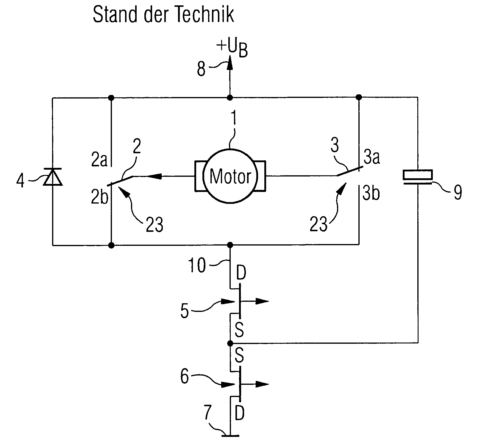
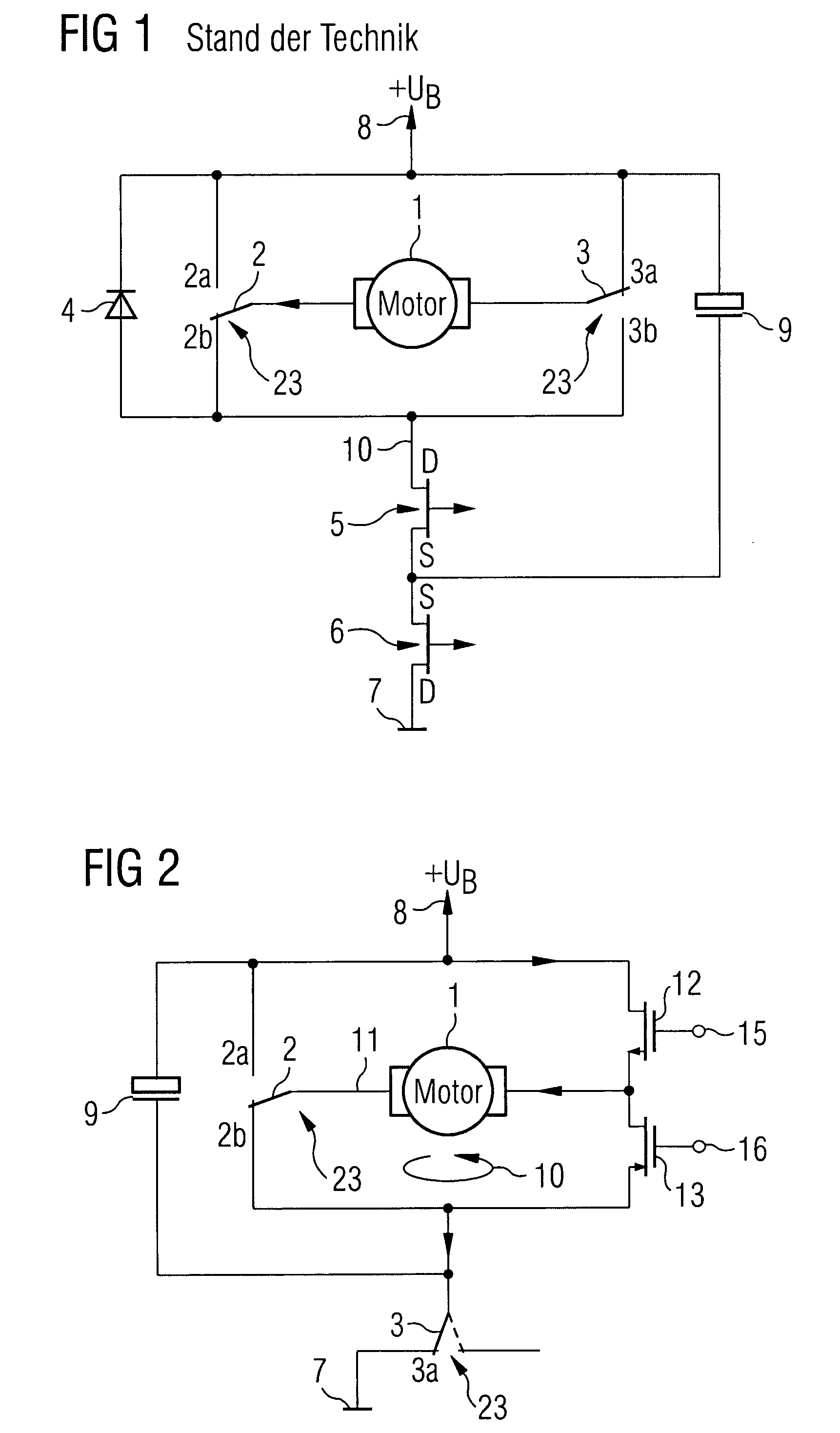
[0016]FIG. 1 shows a circuit diagram for a drive device of a separately activated power window according to the state of the art. The circuit diagram shows a direct-current commutator-motor 1 mounted in the crossarm 11 of a bridge circuit. The sense of rotation of the motor 1 is reversible by way of a polarity-reversing relay 23. The polarity-reversing relay 23 consists of a first electromagnetic system by way of which an operating contact 2 is switchable between two opposite contacts 2a and 2b in the first bridge branch, and of a second electromagnetic system by way of which the operating contact 3 is switchable between two opposite contacts 3a and 3b in the second bridge branch. Depending on the switch position of the contacts of the polarity-reversing relay 23, the motor current flows in the shown crossarm 11 from left to right or—as shown in the circuit configuration of the polarity-reversing relay 23 in FIG. 1—from right to left. Two electronic switches 5 and 6 that are designe...


PUM


Abstract

Device for controling an electrical motor mounted on the crossarm of a bridge circuit whose motor current is controllable with semiconductor components formed in a first bridge branch by an electromagnetic switching device and in a second bridge branch by two serially switched, opposite-phase timed semiconductor switches. The opposite-phase timing of both semiconductor switches creates an active freewheeling branch, thereby making a freewheeling diode unnecessary.

Description

PRIORITY [0001] This application claims priority to German application number 10 2004 008 394.0 filed Feb. 20, 2004. FIELD OF THE INVENTION [0002] The invention concerns a device and method for controlling an electrical motor mounted on the crossarm of a bridge circuit whose motor current is controllable with semiconductor components. BACKGROUND OF THE INVENTION [0003] Bridge circuits with an electrical motor mounted in the crossarm are known from various power electronic circuits. A so-called full-bridge circuit normally consists of four electronic circuits in the bridge branches, of which two at a time are switched in a bridge branch between the supply voltage and the mass. These switches allow to control not only the direction of the motor current in the crossarm but also its magnitude, making it possible to operate the drive system in all four quadrants of the rotational speed-torque-family of curves. [0004] In automobile technology such bridge circuits are used with comfort sys...

Claims


Application Information

Patent Timeline
IPC IPC(8): H02P7/06H02P7/28H02P7/29
CPCH02P7/28
Inventor SVOBODNIK, GREGOR
Owner CONTINENTAL AUTOMOTIVE GMBH
Why Eureka
Try Eureka