Control method of microscope light source

A control method and microscope technology, applied in the field of control, can solve problems such as unstable power output, unstable light source, and slow switching speed

Inactive Publication Date: 2018-12-07
湖南品胜生物技术有限公司
View PDF19 Cites 0 Cited by
  • Summary
  • Abstract
  • Description
  • Claims
  • Application Information

AI Technical Summary

Problems solved by technology

[0003] The problem is: when the load of the power supply changes drastically, the output of the power supply will be unstable, causing the light source to be unstable; when the load of the constant current drive circuit changes drastically, the current stabilization time is relatively longer, resulting in slower switching speed

Method used


Image

  • Control method of microscope light source
  • Control method of microscope light source

Examples


Embodiment Construction

[0019] The present invention will be described in detail below with reference to the drawings in the embodiments of the present invention.

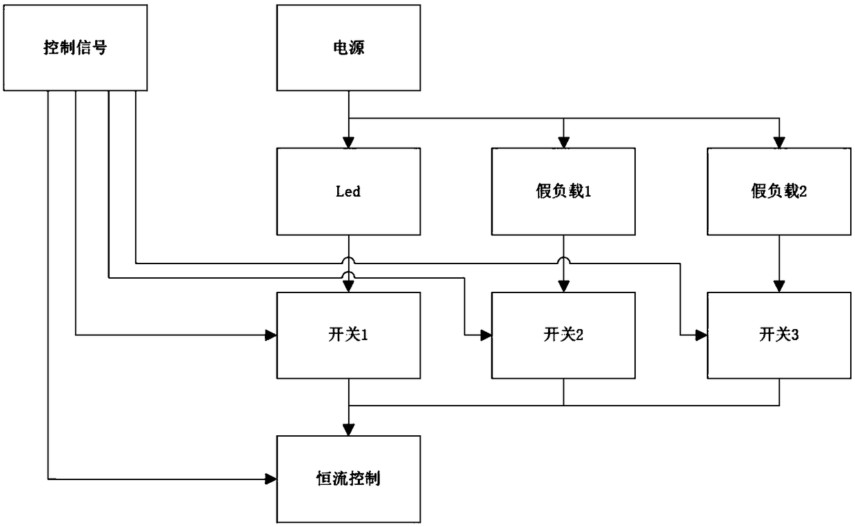
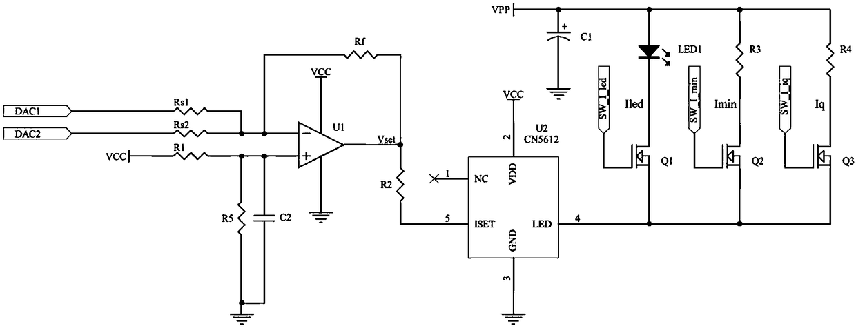
[0020] combine figure 1 and figure 2 As shown, a control method of a microscope light source disclosed in the present invention includes an LED (microscope light source) circuit, a constant current control circuit arranged at the front end of the LED circuit, the microscope light source circuit is connected in series with the constant current control circuit, and the dummy load circuit is used to reduce The constant current circuit and the load change of the power supply, the constant current control circuit is used to set and constant current size.

[0021] Further, the LED circuit is provided with a switch Q1, and the LED circuit is controlled to be turned on and off through the switch Q1;

[0022] As a further scheme of the present invention: for better controlling the LED switches of different wavelengths, the LED circuit is also c...


PUM


Abstract

The invention designs a control method of a microscope light source. Multiple power sources supply power to LEDs of different wavelengths. A dummy load and a high-speed changeover switch are added toan adjustment control circuit. When it is necessary to switch the light sources of different wavelengths, an LED constant-current and power supply circuit required to be turned off is switched to thedummy load, and an LED constant-current and power supply circuit required to be turned on is switched to the LED, thereby reducing the load variation of each constant-current circuit and a power supply, and further increasing the switching speed and improving the stability of the light source.

Description

technical field [0001] The invention relates to a control method, in particular to a control method of a microscope light source. Background technique [0002] The automatic microscope scanning system is a high-precision scanning instrument that has appeared in recent years, and is widely used in medical research, clinical application, biological research and industrial application. In the microphotographing system, it is necessary to use light of various wavelengths to irradiate the specimen (when using a grayscale camera to take pictures, turn on the single-wavelength light to irradiate the specimen, and when using a color camera to take pictures, turn on the white light to irradiate the specimen), each The brightness of the light must be precisely adjustable and stable, and the faster the switching speed between different wavelengths, the better. [0003] The problem is: when the load of the power supply changes drastically, the output of the power supply will be unstabl...

Claims


Application Information

Patent Timeline
Patent Type & Authority Applications(China)
IPC IPC(8): H05B33/08G02B21/06G02B21/00H05B44/00
CPCG02B21/002G02B21/06H05B45/40Y02B20/30
Inventor 贺权源罗军陈小波
Owner 湖南品胜生物技术有限公司
Why Eureka
Try Eureka