
Infusion control valve

A control valve and flow control technology, which is applied in flow control, non-electric variable control, control/regulation system, etc., can solve problems affecting the rehabilitation of patients, infusion tube falling off, and unstable fixing of speed regulating rollers, etc., to achieve the adjustment of infusion flow rate More convenient, more accurate, and stable results

Active Publication Date: 2018-12-11
苏州市百世康医疗器械有限公司
View PDF6 Cites 3 Cited by
  • Summary
  • Abstract
  • Description
  • Claims
  • Application Information

AI Technical Summary

Problems solved by technology

[0002] Infusion is a relatively common treatment method for treating diseases. The flow rate control during the infusion process is generally roughly controlled by a governor formed by a wedge-shaped chute and a speed-regulating roller. The flow rate of the infusion liquid cannot be accurately controlled, and because the wedge With the existence of grooves, the speed regulating roller is unstable and prone to slipping, resulting in an instantaneous acceleration of the flow rate of the liquid medicine, causing discomfort to the patient
[0003] Furthermore, it is sometimes necessary to connect different infusion tubes, but in the prior art, the joints of the infusion tubes are fixed and unstable, which may easily cause the infusion tube to fall off, and the liquid medicine to flow out, resulting in waste of medicine. If detected in time, it will cause the patient's blood to flow back and affect the patient's recovery

Method used


Image

  • Infusion control valve
  • Infusion control valve
  • Infusion control valve

Examples


Embodiment Construction

[0024] The following will clearly and completely describe the technical solutions in the embodiments of the present invention with reference to the accompanying drawings in the embodiments of the present invention. Obviously, the described embodiments are only some, not all, embodiments of the present invention. Based on the embodiments of the present invention, all other embodiments obtained by persons of ordinary skill in the art without creative efforts fall within the protection scope of the present invention.

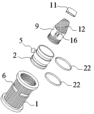
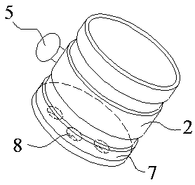
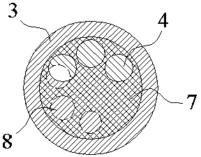
[0025] The invention provides an infusion control valve, which comprises a cylindrical flow-limiting sleeve 1 and a cylindrical regulating tube 2. A flow control plate 3 is fixed on the cross-sectional direction inside the middle section of the flow-limiting sleeve 1. The flow control The plate 3 is provided with a plurality of infusion holes 4, the regulating tube 2 is sleeved in the flow-limiting sleeve 1, the side wall of the regulating tube 2 is provided with a ...


PUM


Abstract

The invention discloses an infusion control valve. The infusion control valve comprises a cylindrical flow limiting tube sleeve and a cylindrical adjusting tube and is characterized in that a flow control plate is fixed in the section direction inside the middle section of the flow limiting tube sleeve, the flow control plate is provided with a plurality of infusion holes, the adjusting tube is nested into the flow limiting tube sleeve, a rotary handle is arranged on the lateral wall of the adjusting tube, a flow adjusting groove for accommodating the rotary handle is arranged in the flow limiting tube sleeve, the adjusting tube can rotate by using the cylindrical center of the flow limiting tube sleeve as the axis, the radial direction of the adjusting tube is provided with a flow adjusting plate, the flow adjusting plate is provided with a plurality of liquid inlets, and two ends of the flow limiting tube sleeve are provided with connectors for being connected with an infusion tube.The infusion control valve is capable of accurately controlling infusion flow speed and guaranteeing flow speed stability.

Description

technical field [0001] The invention relates to the technical field of medical equipment, in particular to an infusion control valve. Background technique [0002] Infusion is a relatively common treatment method for treating diseases. The flow rate control during the infusion process is generally roughly controlled by a governor formed by a wedge-shaped chute and a speed-regulating roller. The flow rate of the infusion liquid cannot be accurately controlled. Due to the existence of grooves, the speed regulating roller is unstable and prone to slipping, resulting in an instantaneous acceleration of the flow rate of the liquid medicine and causing discomfort to the patient. [0003] Furthermore, it is sometimes necessary to connect different infusion tubes, but in the prior art, the joints of the infusion tubes are fixed and unstable, which can easily cause the infusion tube to fall off, the medicinal liquid to flow out, and cause waste of medicine, and even because the infus...

Claims


Application Information

Patent Timeline
IPC IPC(8): A61M5/168
CPCA61M5/16813A61M5/16881A61M2205/3331
Inventor 沈建兴
Owner 苏州市百世康医疗器械有限公司
Learn More