Gas-liquid mixing type jet injection device

An injection device and a gas-liquid mixing technology, which are applied in the field of gas-liquid mixed jet injection devices, and can solve the problems of liquid impact, turbulent flow, and backflow at the corner of a mixing cavity.

Pending Publication Date: 2018-12-11
JIANGSU UNIV ZHENJIANG RES INST OF FLUID ENG EQUIP TECH +1
View PDF0 Cites 2 Cited by
  • Summary
  • Abstract
  • Description
  • Claims
  • Application Information

AI Technical Summary

Problems solved by technology

[0002] The existing gas-liquid hybrid jet injection device has problems of liquid impact and liquid wall attachment when the conical

Method used


Image

  • Gas-liquid mixing type jet injection device
  • Gas-liquid mixing type jet injection device
  • Gas-liquid mixing type jet injection device

Examples


Embodiment Construction

[0019] The present invention will be described in further detail below in conjunction with the accompanying drawings.

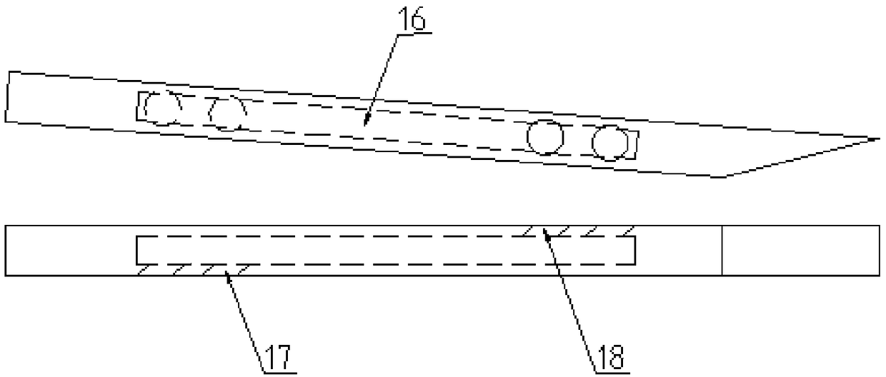
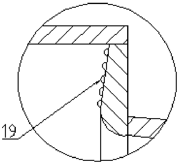
[0020] See attached Figure 1-3 : The gas-liquid mixed jet injection device includes a first mixing chamber part 1, a second mixing chamber part 2, a conical tapering part 3, a diffusing part 4, a water inlet 5, a conical port 6, a gas suction port 7, a conical Shaped part 8, processing liquid inlet 9, compressed gas inlet 10, conical oscillating part 11, rectifying plate 12, diameter section 13, first enlarged diameter section 14, second enlarged diameter section 15, buffer cavity 16, inlet hole 17, Outlet hole 18, hemispherical protrusion 19.

[0021] The first mixing chamber part 1 , the second mixing chamber part 2 , the tapered tapering part 3 and the diffusing part 4 are successively connected adjacently.

[0022] The circumference of the first mixing chamber part 1 is provided with one or more gas suction ports 7, the water inlet 5 is located at the ...


PUM


Abstract

A gas-liquid mixing type jet injection device comprises a first mixing cavity (1), a second mixing cavity (2), a tapered shrinkage portion (3) and a diffusion portion (4) in sequentially adjacent connection. The first mixing cavity is peripherally provided with one or more gas suction inlets (7), and a water inlet (5) is positioned in the center of the first mixing cavity. The second mixing cavity(2) is peripherally provided with one or more treating fluid inlets (9) and a compressed gas inlet (10). The gas-liquid mixing type jet injection device is characterized in that a plurality of rectifying plates (12) are arranged on the inner peripheral wall of the tapered shrinkage portion (3) and internally provided with buffer cavities (16), and one side of each rectifying plate is provided with one or more inlet holes (17) while the other side is provided with one or more outlet holes (18). The gas-liquid mixing type jet injection device has advantages that problems of liquid impact and wall attachment of liquid in flow gathering of the tapered shrinkage portion can be reduced, design of the buffer cavities enables appropriate increasing of the pressure of liquid in a cavity of the tapered shrinkage portion during flow gathering, and a certain pressure increasing effect is achieved.

Description

technical field [0001] The invention relates to the field of fluid injection, in particular to a gas-liquid mixed jet injection device. Background technique [0002] The existing gas-liquid mixed jet injection device has problems of liquid impact and liquid wall attachment when converging at the conical tapered part, pressure loss, backflow and turbulent flow at the corner of the mixing chamber. Contents of the invention [0003] The purpose of the present invention is to overcome the deficiencies in the prior art and provide a gas-liquid mixed jet injection device, which can reduce the liquid impact and liquid adhesion to the wall when the conical tapering part converges. The problem is that the design of the buffer chamber can properly increase the liquid pressure in the chamber of the conical tapered part when the liquid is converging, and has a certain pressurization effect; the design of the raised structure can make the liquid oscillate, and can Suppress backflow an...

Claims


Application Information

Patent Timeline
IPC IPC(8): B05B7/04
CPCB05B7/0416Y02W10/10
Inventor 向清江刘俊陈超许正典
Owner JIANGSU UNIV ZHENJIANG RES INST OF FLUID ENG EQUIP TECH
Why Eureka
Try Eureka