
A rotary stamping die ejection mechanism

A technology of stamping die and ejector mechanism, applied in the field of rotary stamping die ejector mechanism, can solve the problems of high wear rate, short life, high power consumption, etc., and achieve the effects of long life, low noise and power reduction

Active Publication Date: 2019-10-29
广东日信高精密科技股份有限公司
View PDF5 Cites 1 Cited by
  • Summary
  • Abstract
  • Description
  • Claims
  • Application Information

AI Technical Summary

Problems solved by technology

However, the existing ejector mechanism generally includes an ejector rod and a screw drive mechanism, and the use of the screw drive mechanism needs to overcome the helical friction of the screw rod, so that the noise is large, the power consumption is large, the wear rate is large, and the service life is relatively short. short

Method used


Image

  • A rotary stamping die ejection mechanism
  • A rotary stamping die ejection mechanism
  • A rotary stamping die ejection mechanism

Examples


Embodiment 1

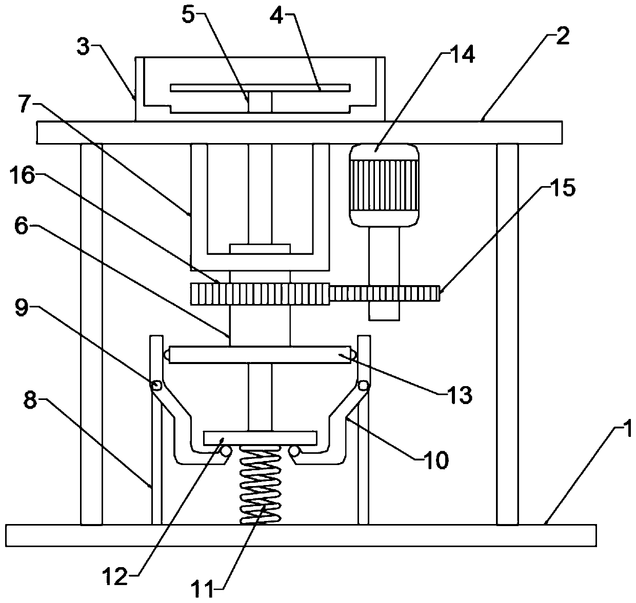
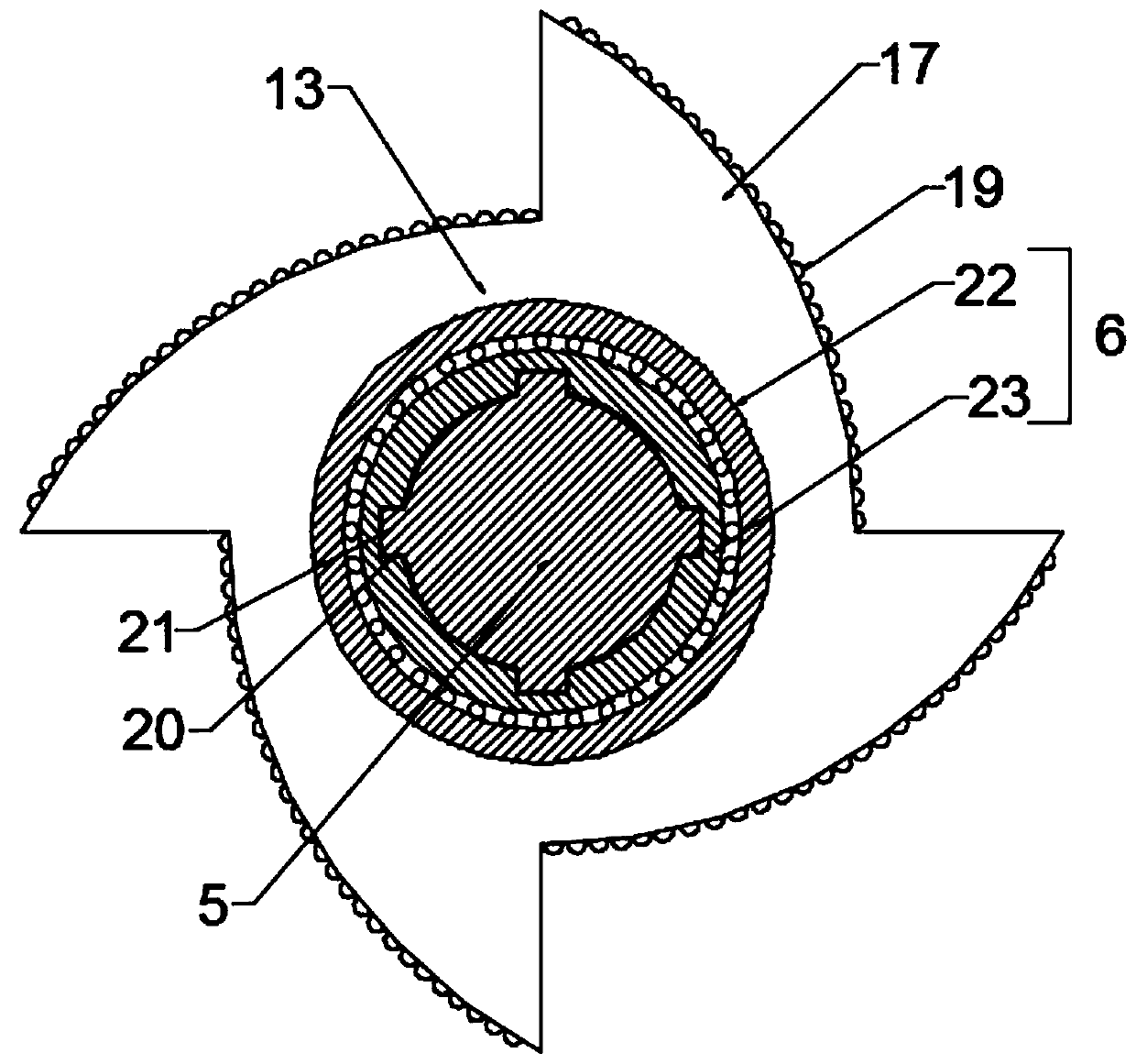
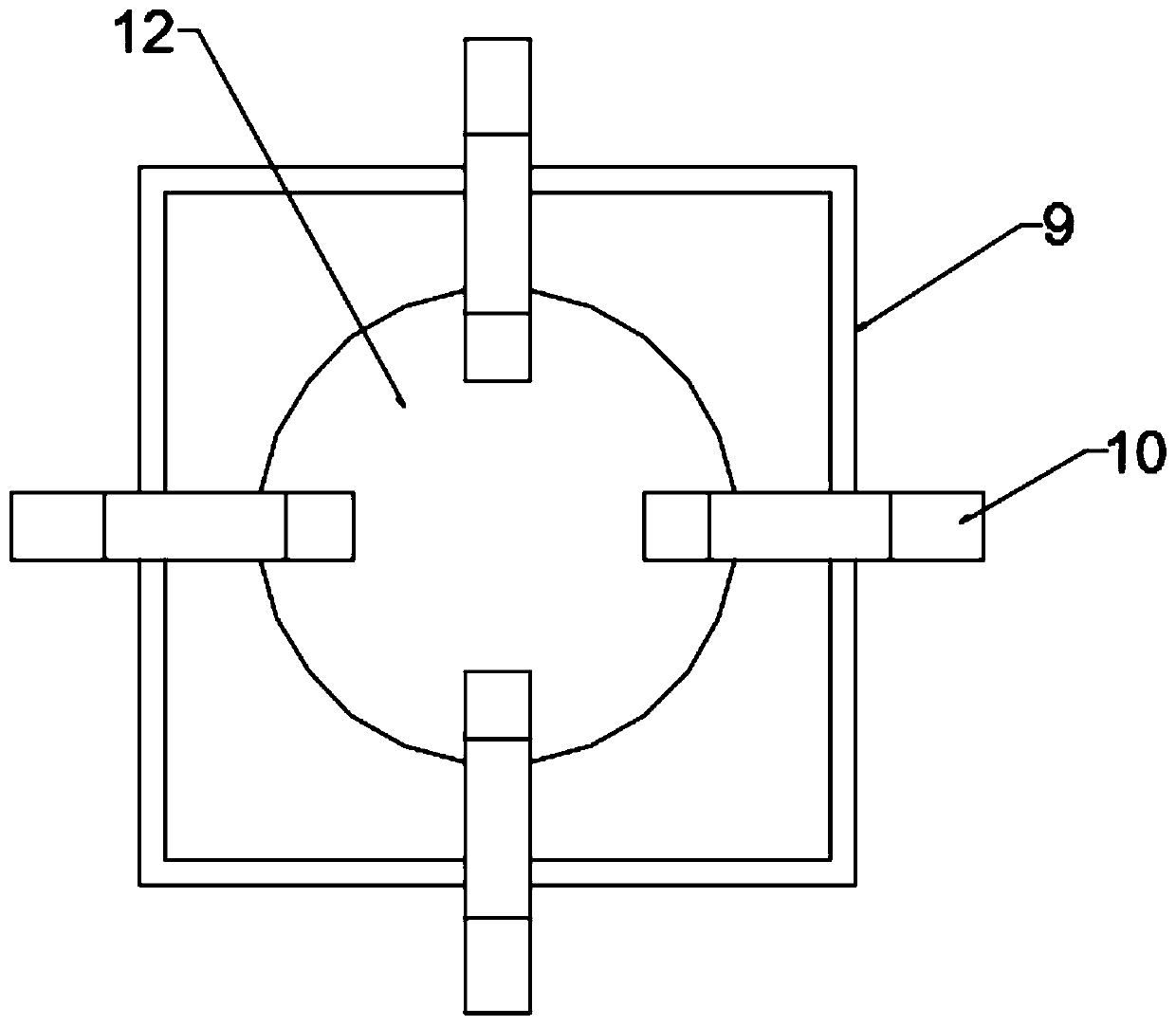
[0020] see Figure 1~3 , in an embodiment of the present invention, a rotary stamping die ejection mechanism includes a base substrate 1, a mold frame 2, a lower mold 3, and a push rod 5 for ejecting the mold, and the mold frame 2 is installed and fixed on the base substrate 1 The upper and lower molds 3 are installed on the upper side of the mold frame 2, and the upper end of the push rod 5 is inserted through the bottom into the inside of the lower mold 3, and the top of the push rod 5 is fixed with a demoulding push plate 4 located in the lower mold 3, and the mold frame 2 A power mechanism for pushing the ejector rod 5 to move vertically is installed on the inside of the inner side, and the power mechanism includes a rotating cylinder 6, a rotating push plate 13, a demoulding motor 14 and four rings arranged around the pushing rod 5 as the center. Toggle the push rod 10, the rotating cylinder 6 is sleeved on the outside of the push rod 5 and the outer wall of the rotating ...

Embodiment 2

[0023] The difference between the present embodiment and the first embodiment is that a plurality of anti-friction balls 19 are installed on the arc-shaped side wall of the arc-shaped pushing part 17 to reduce the friction with the upper end of the push rod 10 wear and tear.


PUM


Abstract

The invention discloses a rotary type stamping die push-out mechanism which comprises a base substrate, a die support, a lower die and a pushing ejection rod used for die stripping. A die stripping push plate located in the lower die is fixed to the top end of the pushing ejection rod, a power mechanism used for pushing the pushing ejection rod to move vertically is installed on the inner side ofthe die support, the power mechanism comprises a rotary barrel, a rotary push plate, a die stripping motor and four stirring push rods circularly arranged with the pushing ejection rod as the center,the rotary barrel is arranged on the outer side of the push ejection rod in a sleeving manner, fixed pin shafts hinged to the four stirring push rods are inserted into the middle portions of the fourstirring push rods in a penetrating manner, four annularly-arranged arc pushing parts are arranged on the outer side of the rotary push plate, and the lower end face of a lower push plate is further connected with the upper end face of the base substrate through a reset spring. By means of the rotary type stamping die push-out mechanism avoids the condition that a traditional lead screw overcomesspiral friction force to push the pushing ejection rod to achieve die stripping, power is reduced, energy consumption is reduced, noise is reduced, the service life is long, and the practicability ishigh.

Description

technical field [0001] The invention relates to the technical field of dies, in particular to a rotary stamping die ejection mechanism. Background technique [0002] With the continuous development of the automobile manufacturing industry. The competition in the automobile industry is becoming more and more intense, and the styling of automobiles is becoming more and more novel. Among the many parts that make up a car, there are various shapes and various forms of part structures, and more and more parts need to be stamped. [0003] The stamping die is a special process equipment that processes materials (metal or non-metal) into parts (or semi-finished products) in cold stamping processing, called cold stamping dies (commonly known as cold stamping dies), stamping is used at room temperature The mold installed on the press applies pressure to the material to cause separation or plastic deformation to obtain a press processing method for the required parts. The materials u...

Claims


Application Information

Patent Timeline
Patent Type & Authority Patents(China)
IPC IPC(8): B21D45/04B21D37/10
CPCB21D37/10B21D45/04
Inventor 刘赞
Owner 广东日信高精密科技股份有限公司
Learn More