Electromagnetic separated brake assist device for automobile

A booster device and automobile technology, applied in the direction of brake transmission, vehicle parts, transportation and packaging, etc., can solve the problems of brake performance degradation, high cost of use, small torque, etc., to achieve fast start-up speed, long service life, The effect of increasing torque

Active Publication Date: 2018-12-11
LIUAN LONGXING AUTO PARTS
View PDF4 Cites 0 Cited by
  • Summary
  • Abstract
  • Description
  • Claims
  • Application Information

AI Technical Summary

Problems solved by technology

However, the car usually includes a power part, a transmission part, and a frame part in terms of structure. In order to make the car start and stop conveniently, the transmission part of the car now usually has a brake device that controls the start and stop. The traditional car brake structure usually uses disc brakes. Structure or drum brake structure, these traditional brake structures usually use hard friction to slow down the speed of the car. During the braking process, sliding friction occurs between the brake parts, and the friction force is used to realize the transmission structure of the car. This kind of friction is hard friction, which will cause greater wear and tear on the brake parts, causing the performance of the brake parts to gradually decline. Therefore, the brake parts in traditional vehicles are vulnerable parts, which need to be replaced frequently, and the use cost is high.
When the car is started, the vehicle needs to be out of the stationary state, so the torque of the vehicle is small when it is started. When the vehicle is on a steep slope or the tire is blocked by an obstacle, the vehicle cannot provide enough torque when it is stationary, and it is difficult to start and move forward, especially Manual vehicles, the car is easy to stall

Method used


Image

  • Electromagnetic separated brake assist device for automobile
  • Electromagnetic separated brake assist device for automobile

Examples


Embodiment Construction

[0013] Below in conjunction with embodiment the present invention is further described:

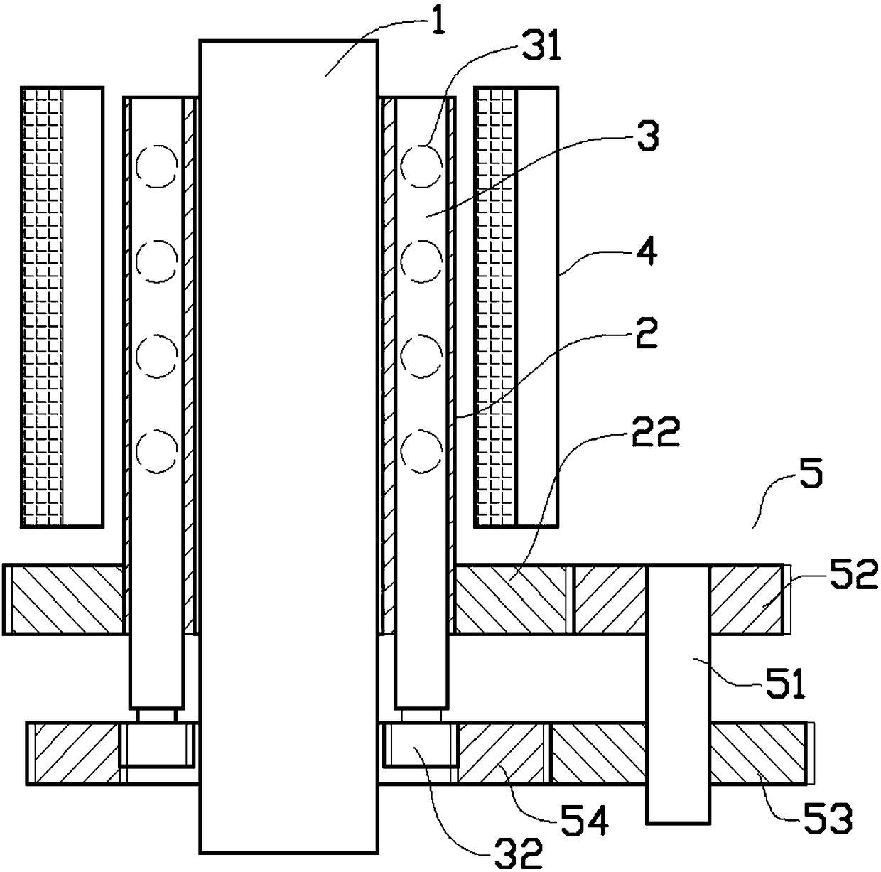
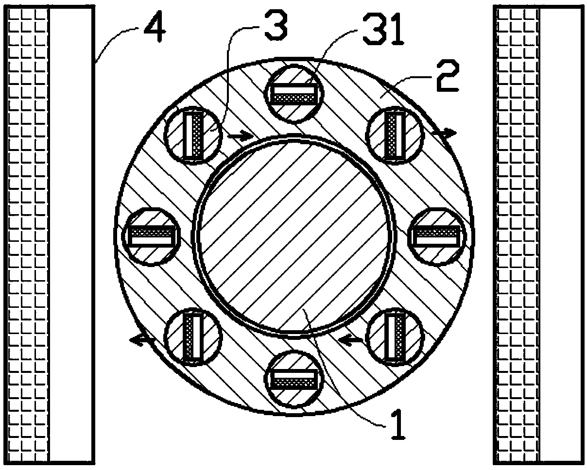
[0014] like figure 1 and figure 2 As shown in the embodiment, the automobile electromagnetic air brake booster device includes a resistance ring 2 assembled on the outside of the transmission shaft 1 of the automobile, the resistance ring 2 is assembled horizontally and coaxially with the transmission shaft 1, and the resistance The ring 2 is processed with mounting holes evenly distributed and horizontally surrounding the axis of the resistance ring 2. A transmission rod 3 that can rotate from the axis is installed in the installation hole. In the transmission rod 3, inner magnetic blocks 31 are uniformly distributed along the axis. The north-south magnetic pole connection line of the inner magnetic block 31 is perpendicular to the axis of the resistance ring 2; the left and right sides of the resistance ring 2 are respectively equipped with electromagnetic plates 4, and one end of the...


PUM


Abstract

An electromagnetic separated brake assist device for an automobile includes a resistance ring arranged on outside the transmission shaft of an automobile; the resistance ring is horizontally and coaxially assembled with the transmission shaft. The resistance ring is provided with mounting holes uniformly distributed and horizontally surrounding the axis of the resistance ring. The mounting hole isprovided with a transmission rod rotatable from the axis. The inner magnetic block uniformly distributed along the axis in the transmission rod. The left and right sides of the resistance ring are respectively provided with an electromagnetic plate, one end of the transmission rod extends out of the mounting hole, one end of the resistance ring is drivingly connected with one end of the transmission rod through a speed changing block, and the resistance ring is fixedly connected with the transmission shaft. The device is used in the deceleration structure of the automobile and does not generate friction in the braking process, so that the wear of the automobile in the braking process can be greatly improved, and the service life of the brake structure of the automobile is longer.

Description

technical field [0001] The invention belongs to the technical field of auto parts, and in particular relates to an automobile electromagnetic air brake booster device. Background technique [0002] Cars now generally refer to non-track-bearing vehicles that are driven by power and have four or more wheels. Cars can be classified according to different types of power, materials used, or types of use. However, the car usually includes a power part, a transmission part, and a frame part in terms of structure. In order to make the car start and stop conveniently, the transmission part of the car now usually has a brake device that controls the start and stop. The traditional car brake structure usually uses disc brakes. Structure or drum brake structure, these traditional brake structures usually use hard friction to slow down the speed of the car. During the braking process, sliding friction occurs between the brake parts, and the friction force is used to realize the transmis...

Claims


Application Information

Patent Timeline
IPC IPC(8): B60T13/74
CPCB60T13/748
Inventor 黄知文
Owner LIUAN LONGXING AUTO PARTS
Why Eureka
Try Eureka