
Dual-fuel internal combustion engine

a dual-fuel, internal combustion engine technology, applied in the direction of special fuel injection apparatus, fuel supply apparatus, structural/machine measurement, etc., can solve the problem of not being able to safely measure even small quantities of liquid fuel

Inactive Publication Date: 2019-07-16
GE JENBACHER
View PDF21 Cites 0 Cited by
  • Summary
  • Abstract
  • Description
  • Claims
  • Application Information

AI Technical Summary

Benefits of technology

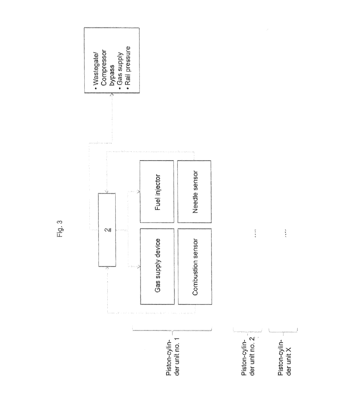
[0016]If a characteristic signal of the combustion is also available, this makes it possible to take account of the course of the combustion in one of the at least two piston-cylinder units during a regulation of the dual-fuel internal combustion engine. It may be provided that the combustion sensor is a knock sensor, a cylinder pressure sensor, a temperature sensor (e.g. arranged in the combustion chamber or exhaust tract) or a NOx probe. In this way, for example, misfires, the occurrence of knocking and the emissions arising during combustion can be taken into account. The combustion can be controlled with knowledge of the cylinder pressure depending on the cylinder pressure. In contrast to the embodiment with only one needle sensor, this makes it possible to operate the dual-fuel internal combustion engine with higher efficiency and / or more favorable emissions.
[0030]It may be provided that a cooling device for the fuel injector is provided. In this way, the coking of liquid fuel or increased wear on the fuel injector and material failure can be prevented. The cooling device can be designed e.g. as liquid cooling device.
[0042]To correct the injection quantity over the lifetime of the fuel injector, it should be mentioned that an injection duration can be extended as well as shortened over the lifetime of a fuel injector due to wear and deposits. The needle sensor gives the possibility of detecting deviations in both directions.

Problems solved by technology

The disadvantage to date was that it was not readily possible to safely meter even small quantities of liquid fuel, but this is necessary in pilot operation.

Method used


Image

  • Dual-fuel internal combustion engine
  • Dual-fuel internal combustion engine
  • Dual-fuel internal combustion engine

Examples


Embodiment Construction

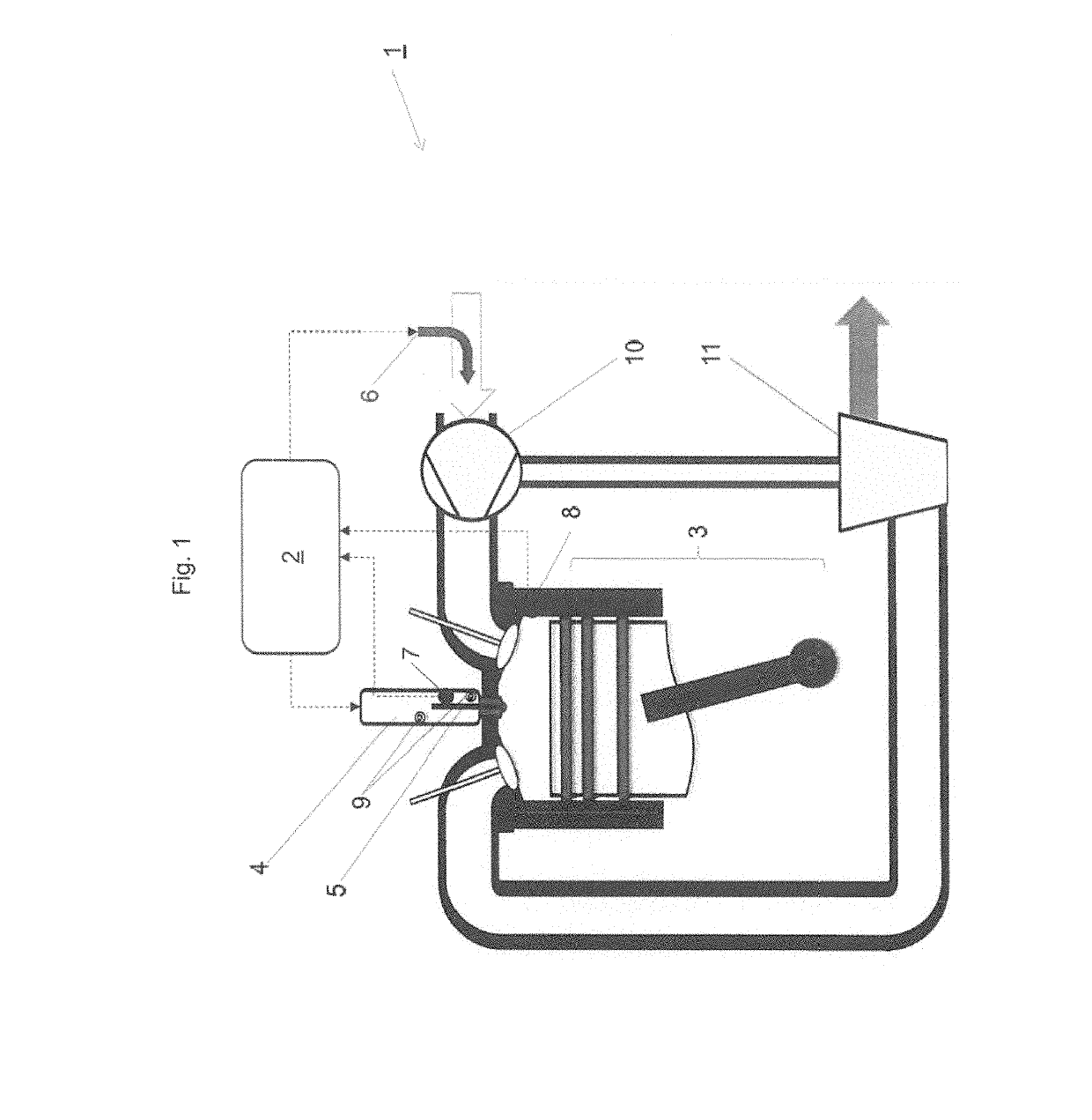
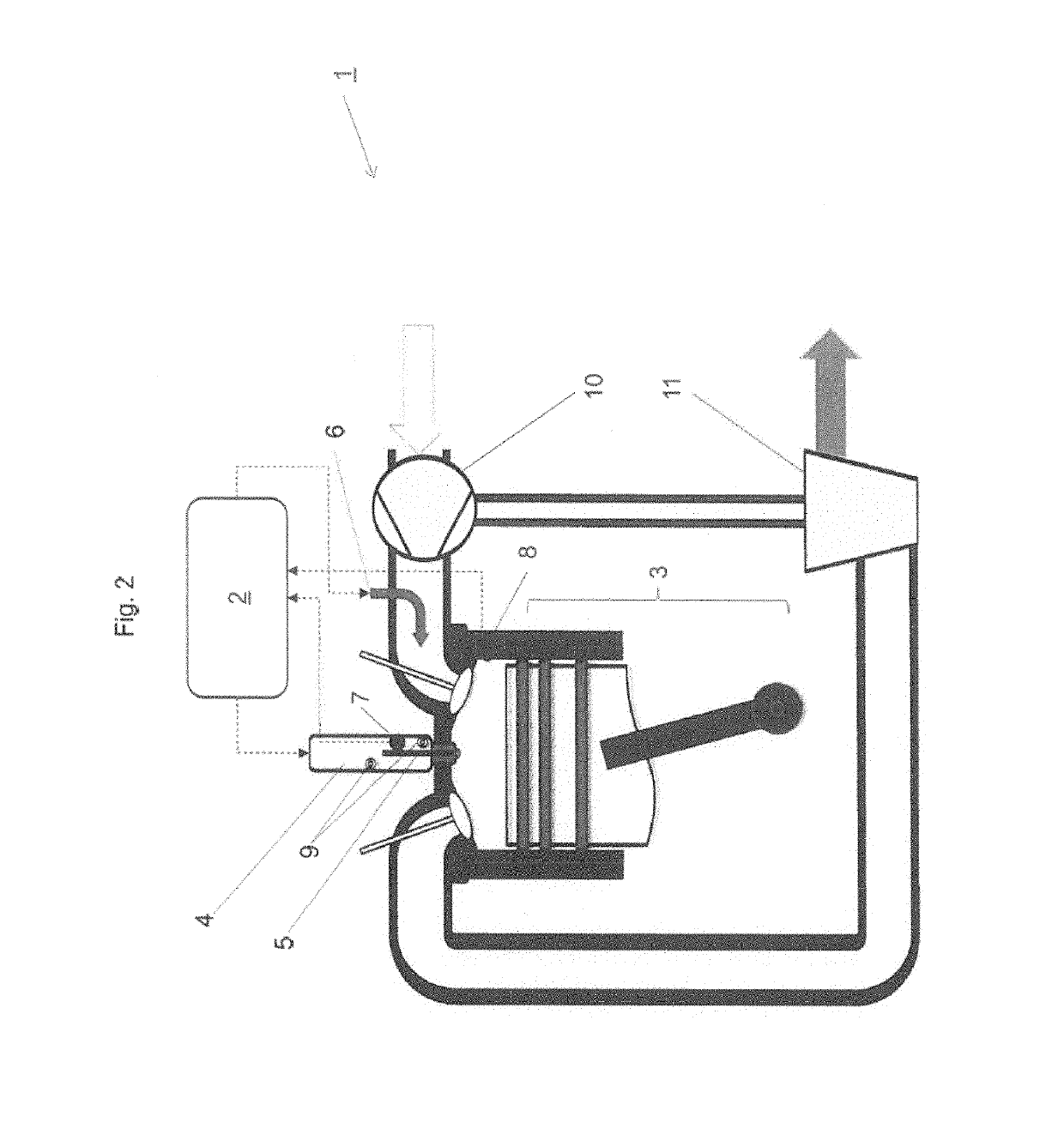
[0048]FIG. 1 shows schematically a piston-cylinder unit 3 of an internal combustion engine 1. A compression device 10 is connected via a shaft to an exhaust turbine 11, in which exhaust gases from the internal combustion engine 1 are expanded. The charge air or an air-fuel mixture to be supplied to the internal combustion engine 1 can be compressed via the compression device 10.

[0049]The piston-cylinder unit 3 of the internal combustion engine 1 can be supplied with gaseous fuel via a gas supply device 6 according to this exemplary embodiment upstream of the compression device 10. Since, in this variant, a mixture of air and fuel gas is compacted, this is called a mixture charge.

[0050]The piston-cylinder unit 3 can be supplied with liquid fuel, e.g. diesel, via the fuel injector 4.

[0051]The corresponding media lines for the liquid and gaseous fuel are not shown for the sake of clarity.

[0052]In this exemplary embodiment, the fuel injector 4 has exactly one injector needle 5. In addit...


PUM


Abstract

A dual-fuel internal combustion engine with a device for regulating the internal combustion engine, with at least two piston-cylinders, a fuel injector assigned to the piston-cylinder units for a liquid fuel, which has an injector needle. Each piston-cylinder unit has a gas supply device for fuel, wherein the regulating device controls the fuel injector and the at least one gas supply device individually for metering of the quantity of the liquid or gaseous fuel supplied to each piston-cylinder unit. At least one needle sensor is connected to the regulating device and assigned to the respective piston-cylinder unit, which detects a characteristic signal of the needle position in the ballistic range, so that the fuel injector can be operated with individual controllability for each of the at least two piston-cylinder units for the regulation of the supplied fuel quantity in the ballistic range.

Description

FIELD OF THE TECHNOLOGY[0001]The invention relates to a dual-fuel internal combustion engine with the features of the preamble of claim 1 and a method for operating a dual-fuel internal combustion engine.BACKGROUND OF THE INVENTION[0002]Generic dual-fuel internal combustion engines are typically operated in two operating modes. We differentiate an operating mode with a primary liquid fuel supply (“liquid operation” for short; in the case of the use of diesel as a liquid fuel, it is called “diesel operation”) and an operating mode with primarily gaseous fuel supply, in which the liquid fuel serves as a pilot fuel for initiating combustion (also called “pilot operation” or “ignition jet operation”).[0003]Whether liquid or pilot operation is selected can depend on various factors, such as the availability of fuel, economic considerations or legal requirements.[0004]It is also known that a pilot mode can be changed to a liquid mode if the quality of the gaseous fuel decreases.[0005]In a...

Claims


Application Information

Patent Timeline
Patent Type & Authority Patents(United States)
IPC IPC(8): F02D19/06F02M57/00F02D19/10F02M65/00F02M43/00F02D41/00F02D41/20F02D35/02F02M61/10F02M21/02F02B75/18
CPCF02D41/0027F02D19/0628F02D19/0642F02D19/105F02D41/008F02D41/0025F02M43/00F02M57/005F02M65/005F02D19/061Y02T10/36F02B75/18F02B2075/1808F02D35/022F02D35/023F02D35/025F02D41/20F02D2200/063F02D2200/0616F02M21/023F02M61/10F02M2200/245F02M2200/247Y02T10/32F02D19/06F02D41/40F02M45/00H02J7/04H02J7/00308Y02T10/30
Inventor FRITZ, JASSIN MARCELIMHOF, DINOTINSCHMANN, GEORGTRAPP, CHRISTIAN
Owner GE JENBACHER
Learn More