Manual transmission

a transmission and manual technology, applied in the direction of belts/chains/gearings, toothed gearings, belts/chains/gearings, etc., can solve the problems of increasing the transmission manufacturing cost, reducing the structural size of the transmission, and increasing the transmission ratio spread, so as to reduce the still existing rotation speed difference, increase wear or even failure, the effect of preventing the effect of failur

Inactive Publication Date: 2012-02-02
ZF FRIEDRICHSHAFEN AG
View PDF3 Cites 0 Cited by
  • Summary
  • Abstract
  • Description
  • Claims
  • Application Information

AI Technical Summary

Benefits of technology

[0013]In a further embodiment of the invention the clutch device of the arrangement for producing a rotation direction reversal of the output shaft is designed in the manner of a synchronizer. In this way increased wear or even failure can be prevented by reducing still existing rotation speed differences between the mating gear concerned and the shaft carrying it.

Problems solved by technology

Overall, this either reduces the structural size of the transmission or results in an increase of transmission ratio spread.
Consequently, this increases the manufacturing costs of the transmission.

Method used


Image

  • Manual transmission
  • Manual transmission
  • Manual transmission

Examples


first embodiment

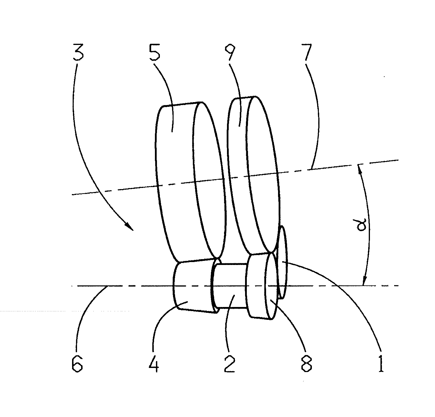
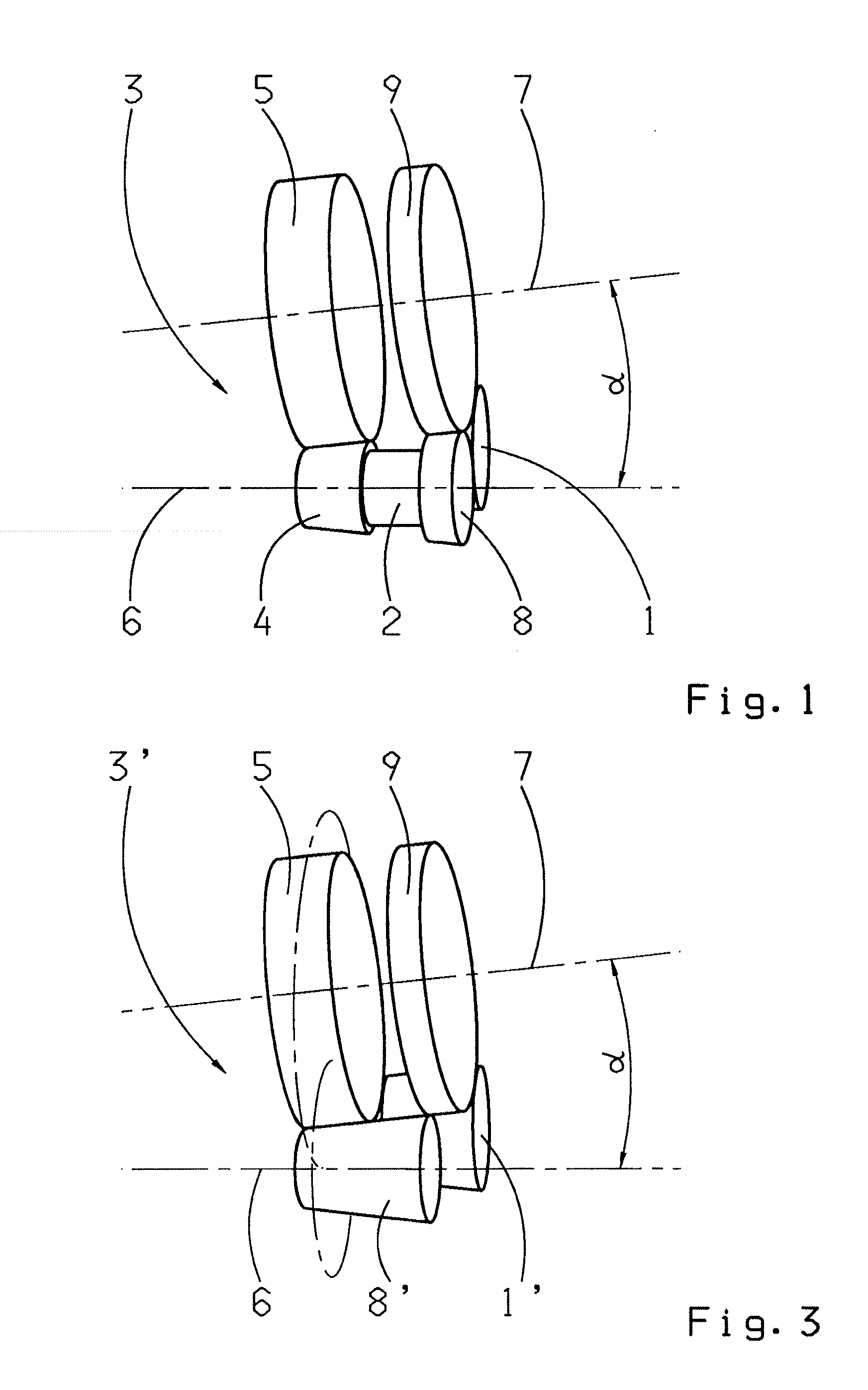
[0018]FIG. 1 shows a perspective view of the manual transmission according to the invention in the area of an intermediate wheel 1. In this area the transmission has an output shaft—not shown here—and a countershaft 2, only part of which can be seen, which can be coupled to the output shaft by means of a shiftable gearwheel pair 3. To those with knowledge of the subject, it will be clear that between the output shaft and the countershaft 2 there must be provided a planetary of gearwheel stages that correspond to the number of transmission gear ratios desired, such that each individual gearwheel pair can be shifted selectively by clutch elements arranged either on the output shaft side or on the countershaft 2 side, by virtue of which the corresponding gear ratio is engaged. It will also be clear that depending on the design of the transmission, the countershaft 2 is either in active connection, via a fixed gearwheel stage, with an input shaft of the transmission, or that it is forme...

second embodiment

[0019]FIG. 3 shows the manual transmission according to the invention in the area of an intermediate wheel 1′. In contrast to the previous embodiment, in this case the contact between the mating gear 8′ and the intermediate wheel 1′ and the contact between the intermediate wheel 1′ and the mating gear 9 do not lie in the same plane. To enable this, the intermediate wheel 1′ is made correspondingly longer in the axial direction. Furthermore, the mating gear 8′ at the same time constitutes the driving-side gearwheel of the shiftable gearwheel pair 3′ and is accordingly also made longer in the axial direction.

INDEXES

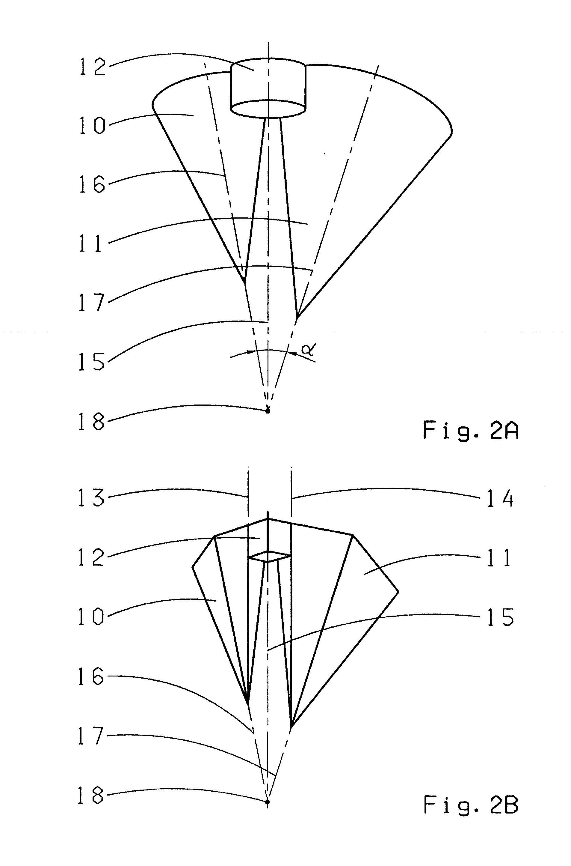
[0020]1, 1′ Intermediate wheel[0021]2 Countershaft[0022]3, 3′ Shiftable gearwheel pair[0023]4 Driving-side gearwheel[0024]5 Driven-side gearwheel[0025]6 Driving-side arrangement axis[0026]7 Driven-side arrangement axis[0027]8, 8′ Driving-side mating gear[0028]9 Driven-side mating gear[0029]10 Roller representing a mating gear[0030]11 Roller representing a mating gear[0031]1...


PUM


Abstract

A manual transmission having an input shaft whose rotation is transmitted to an output shaft by a selected set of gearwheel pairs, which include gearwheels that are positioned on common axes at an angle to one another. The gearwheel pairs each comprise at least one cone-shaped gearwheel. Rotational direction reversal of the output shaft can be produced, upon actuation of a clutch, by an intermediate wheel which is positioned to one side of the arrangement axes and which engages a mating gear located on the driving side and one located on the driven side. At least one of the mating gears is conical and the intermediate wheel is cylindrical and arranged relative to the mating gears such that a rotational axis of the intermediate wheel is parallel to the lines of contact with the mating gears. The rotational axes of the intermediate wheel and each mating gear intersecting at a common point.

Description

[0001]This application is a National Stage completion of PCT / EP2010 / 051609 filed Feb. 10, 2010, which claims priority from German patent application serial no. 10 2009 001 579.5 filed Mar. 16, 2009.FIELD OF THE INVENTION[0002]The invention concerns a manual transmission with an input shaft whose rotational speed and torque can be transmitted, via gearing, to an output shaft by selecting one out of a plurality of shiftable gearwheel pairs formed by gearwheels located respectively on common arrangement axes on the driving and the driven sides, these arrangement axes being positioned at an angle to one another and, to enable this, the gearwheel pairs having in each case at least one conically shaped gearwheel, and such that a rotational direction reversal of the output shaft can be produced, when a clutch device is actuated, by means of an intermediate wheel which is positioned to one side of the arrangement axes and which engages with a mating gear on the driving side and with a matin...

Claims


Application Information

Patent Timeline
Patent Type & Authority Applications(United States)
IPC IPC(8): F16H1/14
CPCF16H3/089Y10T74/1966F16H3/14
Inventor LAMKE, MARTINLANZ, HERMANNLUDESCHER, MICHAELBORNER, JORGBAYER, EWGENI
Owner ZF FRIEDRICHSHAFEN AG
Why Eureka
Try Eureka