
Annular object batch loader and use method thereof as well as elastic ring feeding machine

A technology of rings and loaders, which is applied in the direction of conveyors, conveyor objects, transportation and packaging, etc., can solve the problems that hinder the development of automatic assembly equipment, the labor intensity of manual operation is high, and the size of elastic rings is small, so as to improve Time utilization, ease of accurate operation, and the effect of maintaining accuracy

Pending Publication Date: 2018-12-11
KUNSHAN JIEYUN INTELLIGENT EQUIP CO LTD
View PDF0 Cites 0 Cited by
  • Summary
  • Abstract
  • Description
  • Claims
  • Application Information

AI Technical Summary

Problems solved by technology

[0002] At present, in the field of automatic assembly production lines of automobile engines and new energy motors, when assembling the circlip and the rotor shaft, the circlip is usually placed on the rotor shaft manually and moved to the slot for positioning, and the manual operation is labor-intensive. ,low efficiency
[0003] With the rapid development of intelligent equipment, more and more companies hope to use automation equipment to realize the assembly of the two. When installing automation equipment, it is necessary to keep the axis of the elastic retaining ring as parallel as possible to the rotor axis. It is convenient to fit the elastic rings on the rotor shaft. Therefore, in a feasible solution, a group of elastic rings are usually placed on a shaft in turn and supported by a base, and then the shafts are removed one by one from top to bottom by the reclaiming equipment. The elastic retaining ring on the top is taken out from it for subsequent feeding, assembly and other operations, but because each elastic ring is small in size, easy to deform and small in surface area, when using the above-mentioned feeding structure, no matter whether it is using the jaw clip It is difficult to stably remove each elastic ring from the shaft without holding or vacuum adsorption technology, which also greatly hinders the development of corresponding automatic assembly equipment

Method used


Image

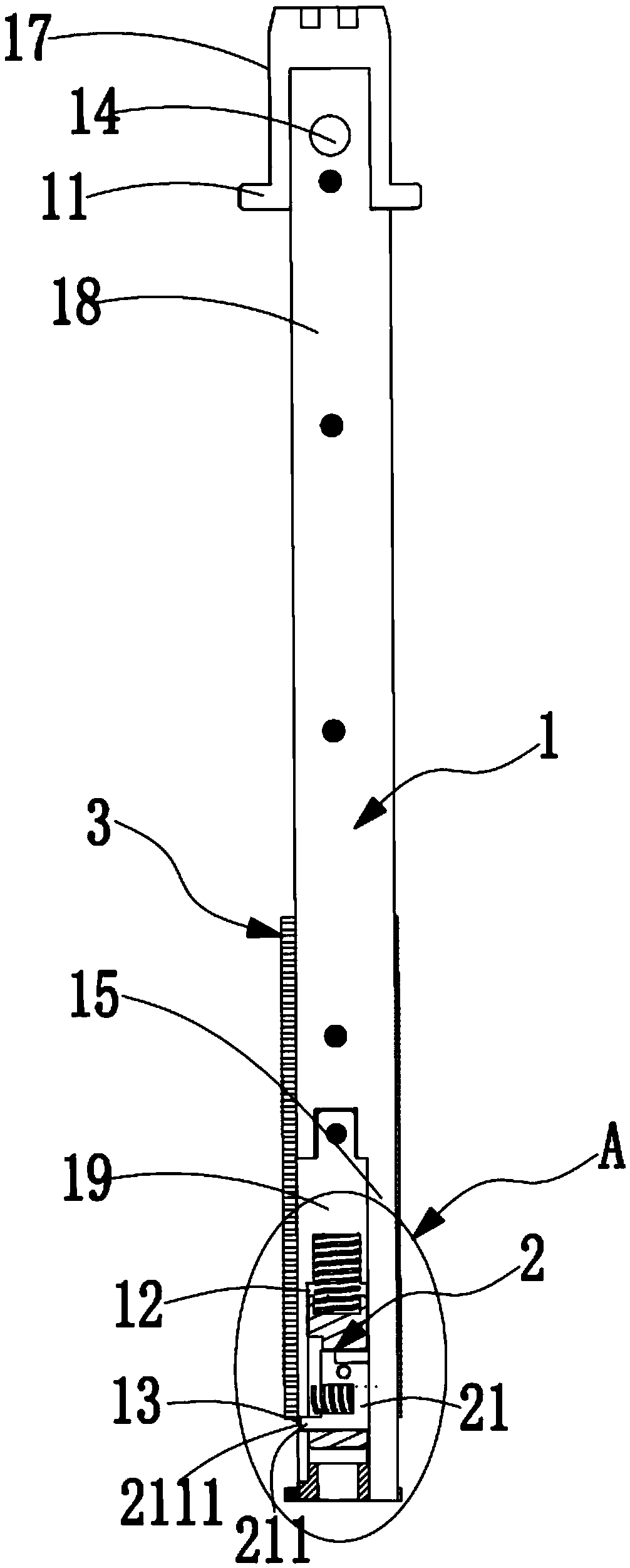
  • Annular object batch loader and use method thereof as well as elastic ring feeding machine
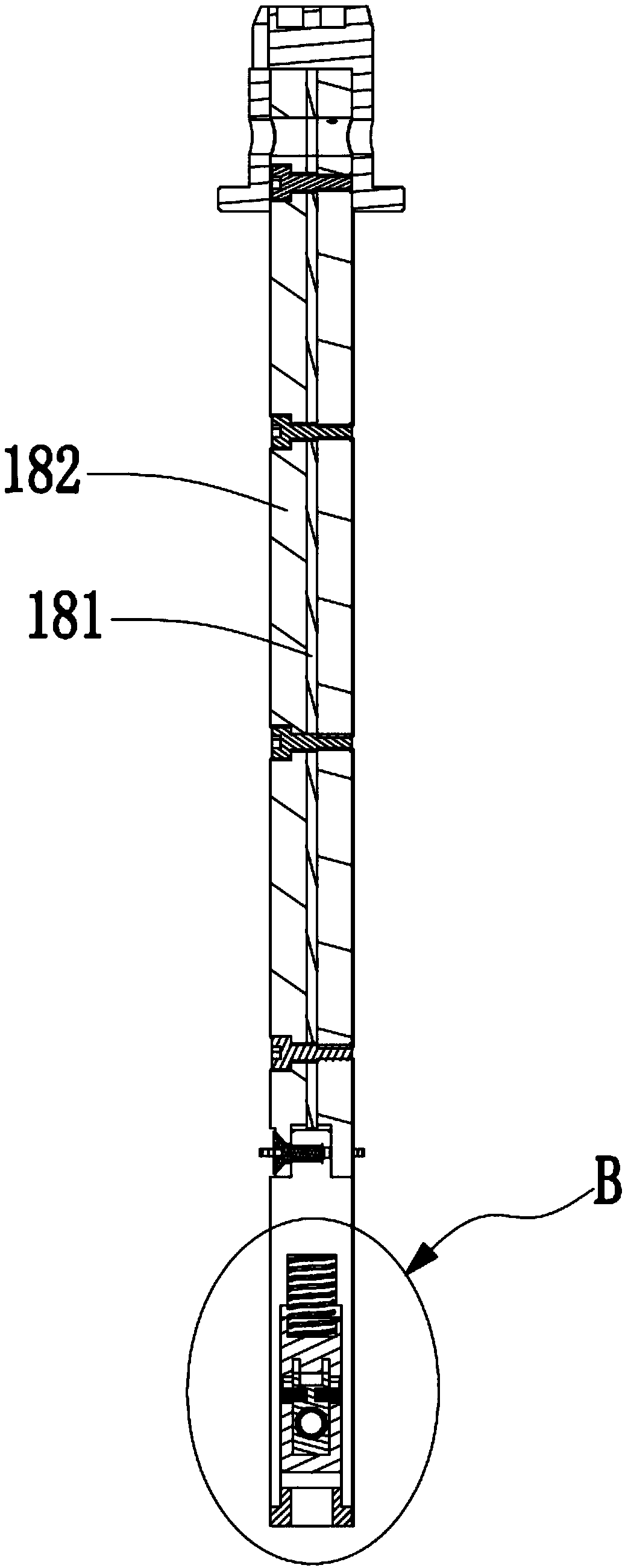
  • Annular object batch loader and use method thereof as well as elastic ring feeding machine
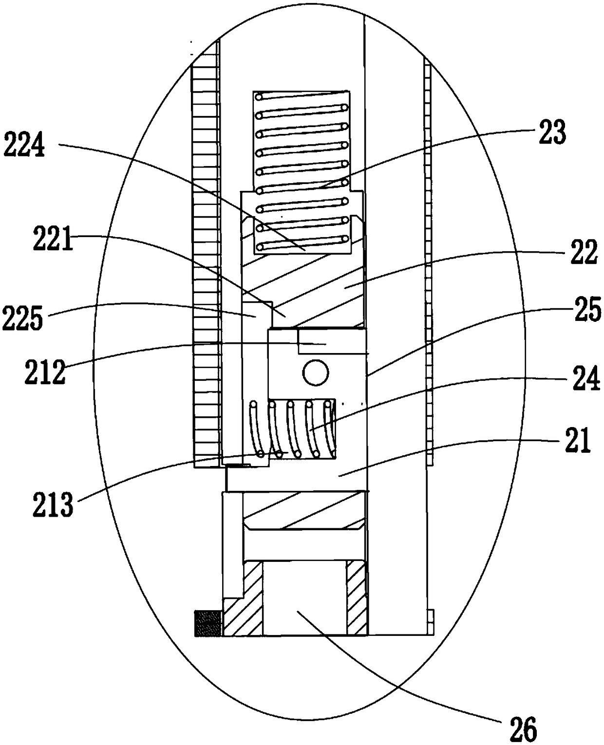
  • Annular object batch loader and use method thereof as well as elastic ring feeding machine

Examples


Embodiment Construction

[0043] The purpose, advantages and characteristics of the present invention will be illustrated and explained through the following non-limiting description of preferred embodiments. These embodiments are only typical examples of applying the technical solutions of the present invention, and any technical solutions formed by equivalent substitutions or equivalent transformations fall within the protection scope of the present invention.

[0044] In the description of the scheme, it should be noted that the terms "center", "upper", "lower", "left", "right", "front", "rear", "vertical", "horizontal", " The orientation or positional relationship indicated by "inner" and "outer" is based on the orientation or positional relationship shown in the drawings, and is only for the convenience of description and simplified description, and does not indicate or imply that the device or element referred to must have a specific orientation , It is constructed and operated in a specific orienta...


PUM


Abstract

The invention discloses an annular object batch loader and a use method thereof as well as an elastic ring feeding machine. The annular object batch loader comprises an outer sleeve, a baffle plate isarranged at one end of the outer sleeve, and a limiting mechanism is arranged in an inner cavity at the other end of the outer sleeve; in a first state, the front end face of a boss of the limiting block in the limiting mechanism is located in the first through hole on the side wall of the outer sleeve; and in a second state, the boss of the limiting block protrudes out of the side wall of the outer sleeve. According to the loader, the method and the machine, the design is ingenious, the limit block is enabled to have two switchable states, in the first state, feeding is carried out, and in the second state, the limiting block can limit the sleeved annular objects, and the sleeved annular objects can be prevented from slipping off the outer sleeve under the self gravity; the number of theannular objects loaded by the annular object batch loader at one step is large so that batch feeding can be realized and transportation and movement are convenient; and meanwhile, when subsequent discharging is carried out, the gravity of an elastic ring can be used for the discharging, so that the problem of difficulty in the discharging is solved, and a foundation is established for the realization of automatic assembly equipment.

Description

Technical field [0001] The invention relates to the field of feeding equipment, in particular to a ring batch loader, its use method and an elastic ring feeder. Background technique [0002] At present, in the field of assembly automation production lines for automobile engines and new energy motors, when the circlip and rotor shaft are assembled, the circlip is usually manually placed on the rotor shaft and moved to the slot for positioning. The manual operation is labor intensive. ,low efficiency. [0003] With the rapid development of intelligent equipment, more and more companies hope to realize the assembly work of the two with the help of automation equipment. When the automation equipment is set, it is necessary to keep the axis of the elastic retaining ring and the rotor shaft as parallel as possible. It is convenient to put the elastic ring on the rotor shaft. Therefore, in a feasible solution, a group of elastic rings are usually put on a shaft in turn and supported by a...

Claims


Application Information

Patent Timeline
Patent Type & Authority Applications(China)
IPC IPC(8): B65G43/08B65G47/74
CPCB65G43/08B65G47/74B65G2201/0214B65G2203/042
Inventor 王杰刘国伟陈伟
Owner KUNSHAN JIEYUN INTELLIGENT EQUIP CO LTD
Learn More