Upwardly-walking concrete conveying device

A conveying device and concrete technology, which is applied in the construction, building structure, construction material processing and other directions, can solve the problems of increasing the running speed, large track impact, and the angle between the moving direction of the trolley line, etc., to avoid deflection, reduce The effect of walking resistance and avoiding meandering motion

Pending Publication Date: 2018-12-11
HEBEI XINDADI ELECTROMECHANICAL MFG
View PDF3 Cites 0 Cited by
  • Summary
  • Abstract
  • Description
  • Claims
  • Application Information

AI Technical Summary

Problems solved by technology

The disadvantage is that in the upward traveling structure, the axis of the guide wheels is set vertically, which is constrained by four sets of guide wheels installed on the running track. Since it needs to pass through the curve, there must be enough clearance between the guide wheels and the track, otherwise it will be blocked. Stuck, due to the existence of this large gap, the body is deflected relative to the track during the running process, the running resistance is large, the noise is large, and due to the deflection of the body, an angle appears in the direction of movement of the trolley line, which reduces the life of the trolley line and reliability
[0006] Whether it is the upper running or lower running structure, there is a defect that the wheel and the body are connected by a rigid bearing seat, which has a large impact on the track and is not conducive to increasing the running speed.

Method used


Image

  • Upwardly-walking concrete conveying device
  • Upwardly-walking concrete conveying device
  • Upwardly-walking concrete conveying device

Examples


Embodiment Construction

[0043] The technical solutions in the embodiments of the present invention are clearly and completely described below in conjunction with the accompanying drawings in the embodiments of the present invention. Obviously, the described embodiments are part of the embodiments of the present invention, not all of them. Based on only the embodiments of the present invention, all other embodiments obtained by those skilled in the art without making creative efforts belong to the protection scope of the present invention.

[0044] In the following description, a lot of specific details are set forth in order to fully understand the present invention, but the present invention can also be implemented in other ways different from those described here, and those skilled in the art can do it without departing from the meaning of the present invention. By analogy, the present invention is therefore not limited to the specific examples disclosed below.

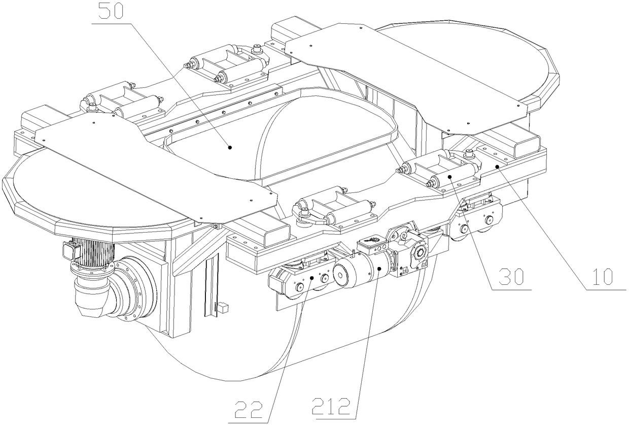
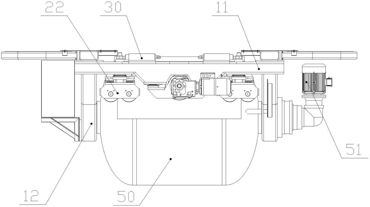
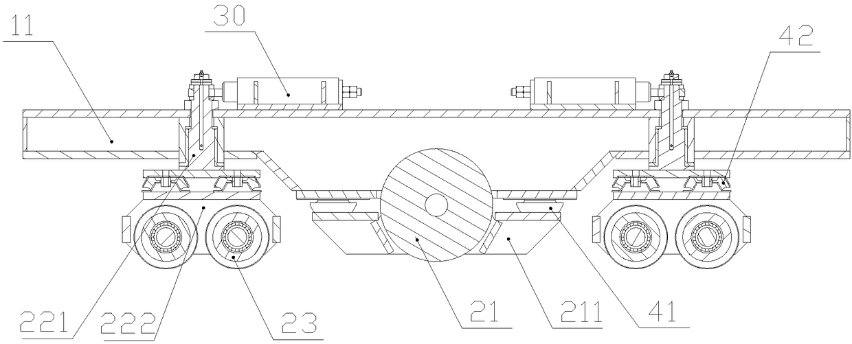
[0045] Such as Figure 1 ~ Figure ...


PUM


Abstract

The invention discloses an upwardly-walking concrete conveying device. The upwardly-walking concrete conveying device helps the defect that a large gap is kept between a guide wheel and a guide rail.Axes of four groups of guide wheels are horizontally arranged on a track. Through arrangement of a guide suspension bracket, the guide wheels rotate at 360 degrees. During turning, the guide wheels are always attached to the track so that an overall device can be fully positioned to the track. The overall device is prevented from deviating in order to reduce walking resistance. After turning, theguide wheels are restored and move straightly through a straightening mechanism. Therefore, hunting motion is prevented. The device adopts the structural form of elastic suspension. Elastic damping parts are arranged between the overall device and all walking mechanisms such that the overall device can be elastically hung on the track. During the travelling process of the overall device, the device is prevented from jolting caused by the uneven track. The device travels smoothly and steadily, thereby reducing impact on the track. The walking speed increases.

Description

technical field [0001] The invention relates to the field of concrete conveying devices, in particular to an upward traveling concrete conveying device. Background technique [0002] At present, in the industrial production of prefabricated components in the field of construction, a transport hopper with a power source is generally used to transport concrete between the concrete mixing station and the concrete placing machine. [0003] The existing conveying materials are divided into two types: up-running and down-running. [0004] For example, a transport hopper driven by a tractor trolley disclosed in Chinese utility model patent ZL201520465252.1, and a precast concrete transport vehicle disclosed in Chinese invention patent ZL201010161137.7, both of which have a downward traveling structure. The remarkable feature of the down-travel structure is that a tractor is needed to pull the hopper forward, and a connecting rod (or coupling) is required to be hinged between the t...

Claims


Application Information

Patent Timeline
IPC IPC(8): E04G21/02
CPCE04G21/02
Inventor 赵保久张紫旭李建峰王瑞平孙景杰曹文华王月
Owner HEBEI XINDADI ELECTROMECHANICAL MFG
Why Eureka
Try Eureka