Rotary heating device for large impeller installation

A technology of rotating heating and impeller, applied in lighting and heating equipment, combustion type, metal processing, etc., can solve the problems of worker danger, aggravating production accidents, large volume and weight of large impellers, etc., to reduce the risk of accidental contact burns, reduce Process complexity and the effect of reducing the occupied time

Inactive Publication Date: 2018-12-11
HARBIN UNIV OF SCI & TECH
View PDF5 Cites 0 Cited by
  • Summary
  • Abstract
  • Description
  • Claims
  • Application Information

AI Technical Summary

Problems solved by technology

[0003] 1. During the heating process, workers with spray guns need to move at a constant speed under the impeller to ensure uniform heating. Due to various human reasons, this heating uniformity is usually not ideal
2. Large impellers are bulky and heavy (typically several tons)
In the process of hoisting and heating, once it is accidentally hoisted and fixed, it will be very dangerous to the workers under the impeller and will aggravate the occurrence of production accidents
3. Using the traditional method requires multiple steps of hoisting the impeller in advance, moving it off the ground, manual heating, and manual unloading, which is not only time-consuming and labor-intensive, but also inefficient

Method used


Image

  • Rotary heating device for large impeller installation
  • Rotary heating device for large impeller installation
  • Rotary heating device for large impeller installation

Examples


Embodiment Construction

[0022] The following will clearly and completely describe the technical solutions in the embodiments of the present invention with reference to the accompanying drawings in the embodiments of the present invention. Obviously, the described embodiments are only some, not all, embodiments of the present invention. Based on the embodiments of the present invention, all other embodiments obtained by persons of ordinary skill in the art without making creative efforts belong to the protection scope of the present invention.

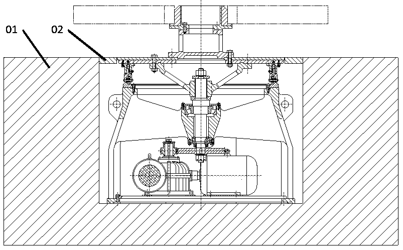
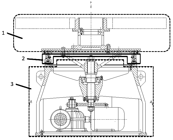
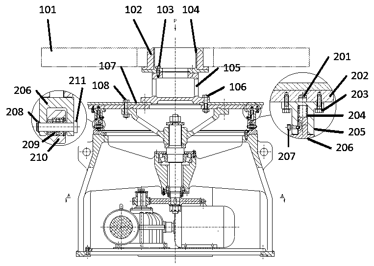
[0023] like figure 1 , figure 2 As shown, a rotating heating device for installing a large impeller, including a heat-insulating support part (1), a rotating part (2), and a power part (3), is characterized in that: the heat-insulating support part (1) Above the ground, the rotating part (2) and the power part (3) are buried underground, wherein the top of the rotating part (2) is flush with the ground (01) and the pedal (02);

[0024] Furthermore, a rotat...


PUM


Abstract

The invention discloses a rotary heating device for large impeller installation. The rotary heating device for large impeller installation comprises a heat insulating support part, a rotary part, anda power part, and is characterized in that the heat insulation support part is above the ground, the rotary part and the power part are buried underground, wherein the top end of the rotary part is flushed with the ground and pedals. The heat insulating support part further comprises heat insulating sleeves, impellers are connected to the outer parts of the heat insulating sleeves, and support sleeves are connected to the inner parts of the heat insulating sleeves in a interference fit mode, the support sleeves are fixedly connected with heat-resisting support bodies through first connecting bolts, and the heat-resisting support bodies are fixedly connected with upper bottom plates and lower bottom plates in the rotary part through second connecting bolts. The rotary heating device for large impeller installation has the advantages that first, a way of traditional manual spray gun rotary heating is changed, rotors can rotate, and heating points can be fixed; second, the support part and the rotary part are connected by using the bolts, and replacement is convenient; and third, the machine is semi-buried underground, the overall occupied space is reduced, and manual heat treatment is convenient.

Description

technical field [0001] The invention relates to a rotary heating device for large impeller installations. Background technique [0002] At present, in the actual production, the assembly process of the large impeller still adopts a completely manual production method, that is, firstly, the impeller is manually installed on the crane in the factory building, and then the crane is lifted off the ground by manual operation, and then the worker holds the heating device. The spray gun is manually heated under the impeller lifted by the crane, and the workers need to keep moving during the heating process. After a brief summary, it can be found that the production method used in actual production at this stage has the following disadvantages. [0003] 1. During the heating process, workers with spray guns need to move at a constant speed under the impeller to ensure uniform heating. Due to various human reasons, this heating uniformity is usually not ideal. 2. Large impellers ...

Claims


Application Information

Patent Timeline
Patent Type & Authority Applications(China)
IPC IPC(8): F23D14/38F23D14/46B23P11/02
CPCF23D14/38B23P11/025F23D14/465
Inventor 张元崔贺新
Owner HARBIN UNIV OF SCI & TECH
Why Eureka
Try Eureka