Eureka AIR delivers breakthrough ideas for toughest innovation challenges, trusted by R&D personnel around the world.

Method for determining air leak holes, vacuum motor and method for detecting article adsorbed by vacuum motor

A technology of a vacuum motor and a determination method, which is applied to the detection of vacuum motors and their adsorbed objects, and the determination of air leakage holes, can solve the problem of the adsorption of objects by the motor, the difficulty of setting the current change threshold, and the difficulty of correctly judging whether the vacuum motor really adsorbs objects, etc. problem, to achieve the effect of improving the accuracy

Active Publication Date: 2018-12-11
河北盛世天昕电子科技有限公司
View PDF18 Cites 2 Cited by
  • Summary
  • Abstract
  • Description
  • Claims
  • Application Information

AI Technical Summary

Problems solved by technology

[0003] At present, it is generally detected whether the vacuum motor has attracted the object by detecting whether the change value between the current before the vacuum motor absorbs the object and the current after it absorbs the object exceeds the current change threshold. The difference between the subsequent currents is small, making it difficult to set the current change threshold
If the change threshold is set small, it may cause the vacuum motor to not hold the object but it is judged as a successful adsorption. If the change threshold is set to a large value, it may cause the vacuum motor to successfully hold the object, but it is judged not to hold it, causing the motor to repeatedly absorb the object. , into an infinite loop
Therefore, through the existing technology, it is difficult to correctly judge whether the vacuum motor is really sucking the object, and there is a problem of inaccurate judgment

Method used


Image

  • Method for determining air leak holes, vacuum motor and method for detecting article adsorbed by vacuum motor
  • Method for determining air leak holes, vacuum motor and method for detecting article adsorbed by vacuum motor
  • Method for determining air leak holes, vacuum motor and method for detecting article adsorbed by vacuum motor

Examples


specific Embodiment

[0113] According to the above description, the present application also provides an embodiment of a method for determining an air leak, a vacuum motor and a method for detecting its adsorbed articles, including a medicine dispensing device, the medicine dispensing device is equipped with a main board, a vacuum motor , vacuum manipulator, etc., wherein the main board, vacuum motor, and vacuum manipulator are connected by data signal lines, and the end of the vacuum manipulator is provided with a vacuum suction cup, which is used to absorb medicines.

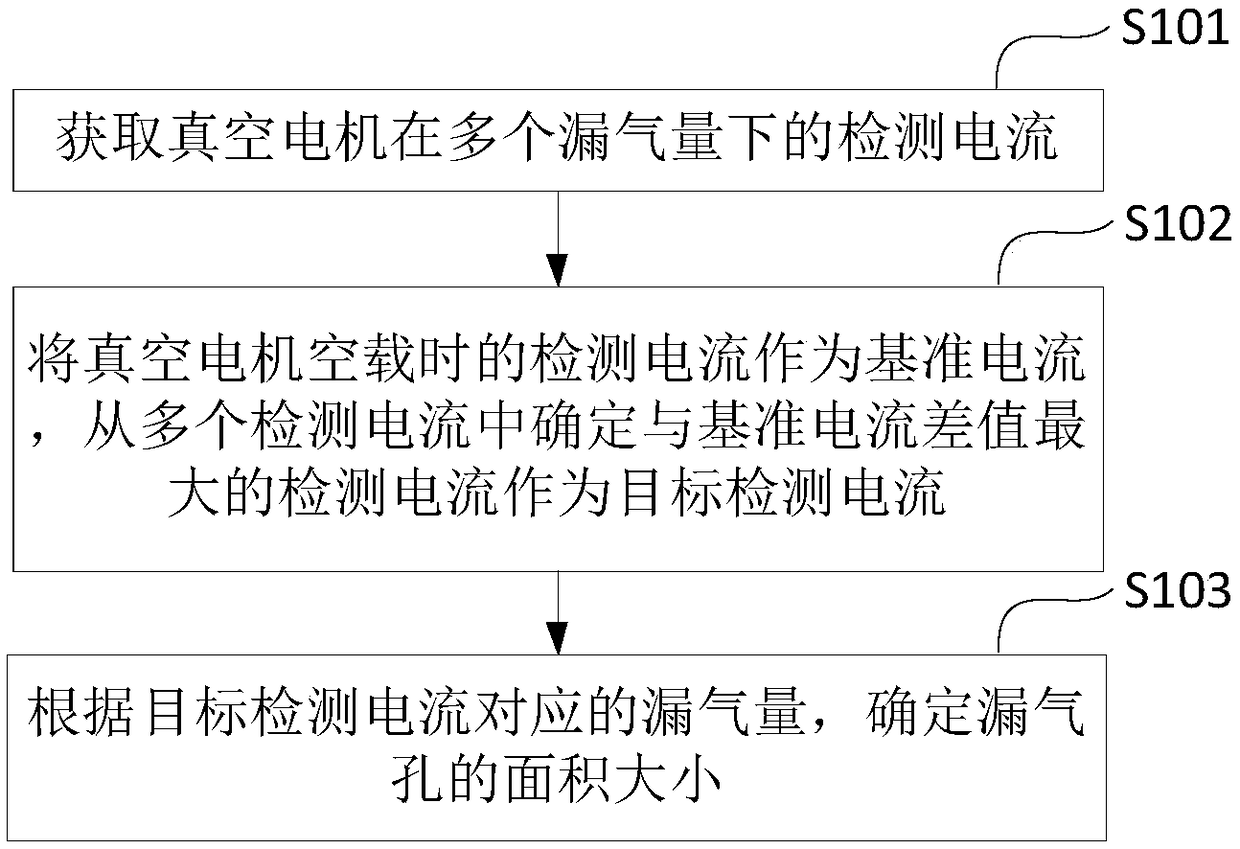
[0114] Apply a method for determining an air leak hole, a vacuum motor and its adsorbed article detection method provided in the embodiment of the present application to the medicine dispensing device, and obtain the detection current of the vacuum motor of the medicine dispensing device under multiple air leakage amounts, Then determine the detection current with the largest difference from the reference current when the vacuum mo...


PUM


Abstract

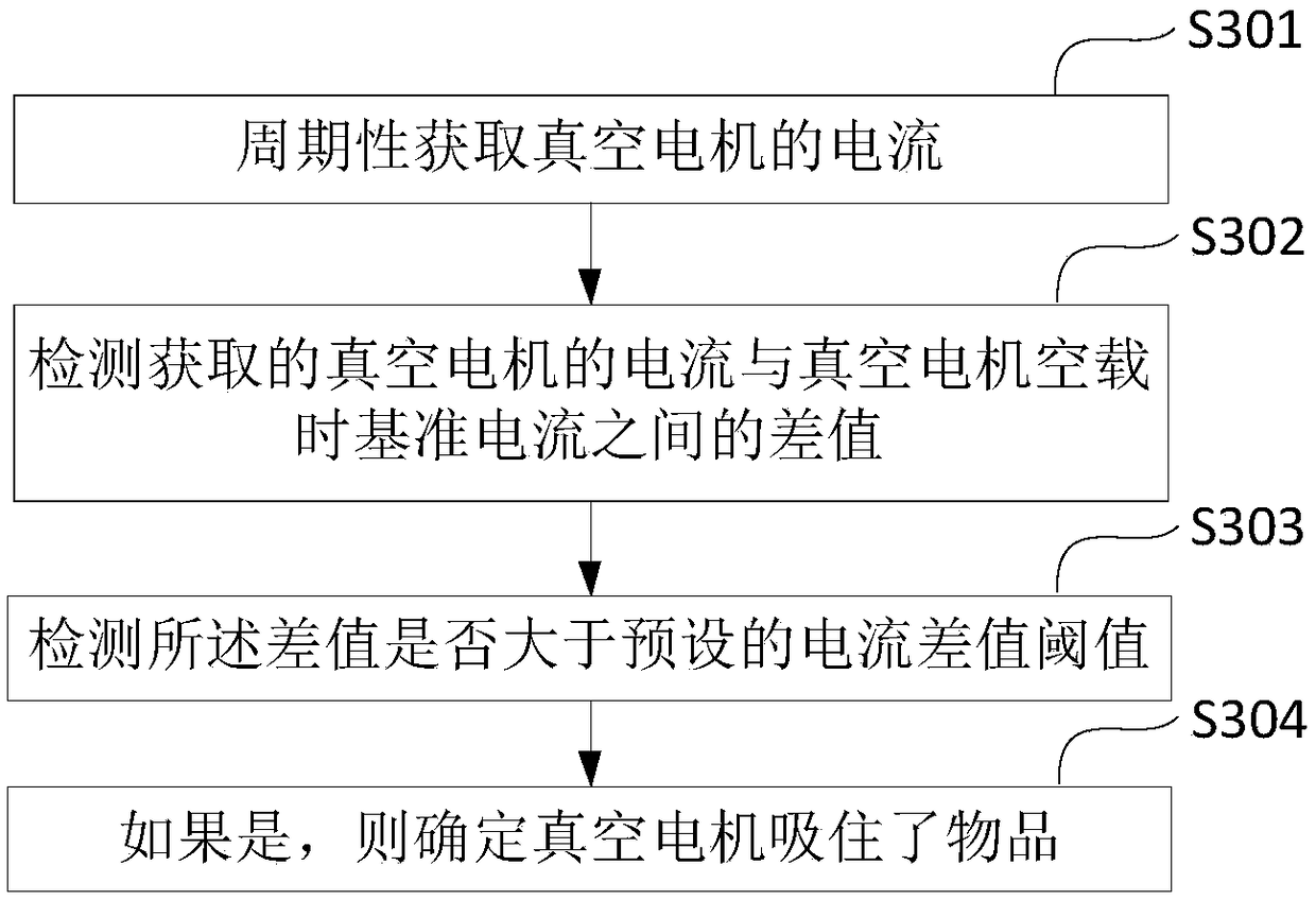
The invention provides a method for determining air leak holes, a vacuum motor and a method for detecting an article adsorbed by the vacuum motor. The method for determining air leak holes comprises the steps of determining a detection current with a largest difference from a reference current when the vacuum motor is in a no-load state from a plurality of detection current as the target detectioncurrent by obtaining a detection current of the vacuum motor under a plurality of air leak amounts, and determining the size of an area of the air leak holes according to the air leak amount corresponding to the target detection current. The air leak holes of corresponding sizes are arranged in a pipe between the vacuum motor and a vacuum sucker. The method for detecting an article adsorbed by the vacuum motor comprises the steps of periodically obtaining the current of the vacuum motor when the vacuum motor is used to absorb the article, detecting a difference between a vacuum motor currentand the reference current when the vacuum motor is in the no-load state, and determining that the vacuum adsorbs the article when the difference is larger than a preset current difference threshold. Compared with a conventional method, the methods of the embodiment of the invention have the advantages that the structural complexity and cost are reduced, the accuracy and reliability of a detectionresult are improved, and the methods are easier to realize.

Description

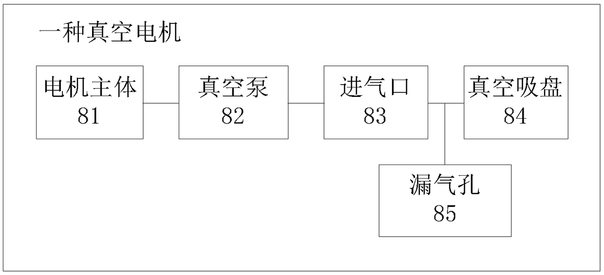
technical field [0001] The present application relates to the technical field of current feedback signals, in particular to a method for determining an air leak hole, a vacuum motor and a method for detecting an adsorbed object thereof. Background technique [0002] With the development of science and technology, the application of current feedback signal has involved in the fields of industry, scientific research, medical treatment, etc. The richness of the feedback signal determines the breadth of its application. The technology of controlling the speed of the motor through the change of the current is mature, and the current of the conventional motor is proportional to the load, but the vacuum motor does not completely follow this rule. The vacuum motor integrates an ordinary motor and a vacuum pump, and the motor provides power for the vacuum pump. The vacuum pump is connected to the vacuum suction cup, and the vacuum suction cup can be used to absorb objects. [0003] ...

Claims


Application Information

Patent Timeline
IPC IPC(8): G01B7/32G01V3/08F04B37/14F04B35/04
CPCF04B35/04F04B37/14G01B7/32G01V3/08
Inventor 王志宏
Owner 河北盛世天昕电子科技有限公司
Why Eureka
Eureka Blog
Learn More