Battery internal resistance measuring method and device for vehicle

A technology of battery internal resistance and measurement method, which is applied in the direction of measuring device, measuring electricity, measuring electric variable, etc.

Inactive Publication Date: 2018-12-11
CHONGQING WIRELESS OASIS COMM TECHCO
View PDF5 Cites 2 Cited by
  • Summary
  • Abstract
  • Description
  • Claims
  • Application Information

AI Technical Summary

Problems solved by technology

[0003] The battery internal resistance measurement method and device provided by the present invention mainly solve the technical problem that in the prior art, when measuring the internal resistance of a vehicle battery, it is mostly realized by offline measurement with an internal resistance meter, and it is impossible to measure the internal resistance of a vehicle battery. The problem of dynamic real-time measurement of the internal resistance of the battery

Method used


Image

  • Battery internal resistance measuring method and device for vehicle
  • Battery internal resistance measuring method and device for vehicle
  • Battery internal resistance measuring method and device for vehicle

Examples


Embodiment 1

[0063] for car batteries

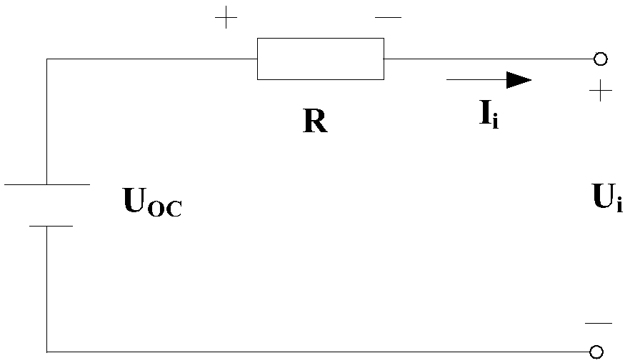
[0064] See figure 1 as shown, figure 1 It is a schematic diagram of the circuit structure of a vehicle battery unit to be tested in this embodiment, wherein U OC R is the power supply electromotive force of the vehicle battery unit to be tested. The power supply electromotive force is a fixed value. R is the internal resistance of the vehicle battery unit to be tested. It should be noted that, generally speaking, the internal resistance of the power supply is not A constant value, usually, the internal resistance of the power supply is related to the current or voltage passing through the power supply, U i is the external apparent voltage of the vehicle battery unit to be tested, that is, the road terminal output voltage of the vehicle battery unit to be tested, and is used to supply power to the load connected to the vehicle battery unit to be tested, I i In order to flow the current of the internal resistance of the vehicle battery unit to be te...

Embodiment 2

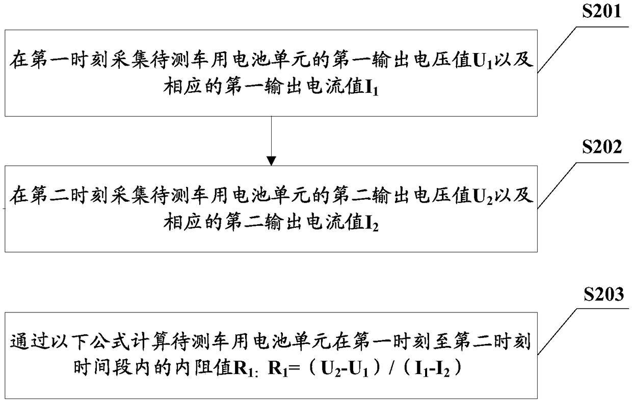
[0111] See Figure 6 As shown, this embodiment provides a vehicle battery internal resistance measurement device, including a collection module 61 and a calculation module 62, wherein the collection module 61 is used to collect the first output voltage value of the vehicle battery unit to be tested at the first moment u 1 and the corresponding first output current value I 1 , and collect the second output voltage value U of the vehicle battery unit to be tested at the second moment 2 and the corresponding second output current value I 2 ; The calculation module 62 is used to pass the formula "R 1 =(U 2 -U 1 ) / (I 1 -I 2 )” to calculate the internal resistance value R of the vehicle battery unit to be tested in the time period from the first moment to the second moment 1 , the function of the acquisition module 61 in this embodiment can be realized by constructing corresponding peripheral circuits.

[0112] It should be understood that the second moment in this embodime...


PUM


Abstract

The embodiment of the invention provides a battery internal resistance measuring method and device for vehicle. The method includes the steps of acquiring the first output voltage value U1 of a battery unit to be detected and the corresponding first output current value I1 at the first moment, acquiring a second output voltage value U2 of the battery unit to be detected and a corresponding secondoutput current value I2 at the second moment, and then calculating the internal resistance R1 of the battery cell unit for the vehicle to be detected at a first moment to a second moment by using theformula " R1 = (U2 - U1) / (I1-I2)", that is the internal resistance corresponding to a time period between two moments of the vehicle battery unit to be measured is calculated by collecting the outputvoltage and the output current of vehicle battery unit to be measured at two different moments. According to the scheme, the internal resistance values of the vehicle battery cells to be measured under different time periods can be measured, so that the internal resistance of the vehicle battery cells to be measured can be dynamically measured in real time in the using process.

Description

technical field [0001] The invention relates to the technical field of electric vehicle power batteries, in particular to a method and device for measuring the internal resistance of a vehicle battery. Background technique [0002] With the development of science and technology, electric vehicles are becoming more and more popular. Most of the power sources of existing electric vehicles rely on lithium batteries. Accurately judging the health status of lithium batteries is a prerequisite for the safe use of lithium batteries. Most of the existing lithium battery management technologies The health status of lithium batteries is judged by monitoring parameters such as voltage, current, temperature, and cycle life. However, the internal resistance, which is the most intuitive reflection of the health parameters of lithium batteries, cannot be detected in real time. The existing method for measuring the internal resistance of lithium batteries for vehicles is mainly offline meas...

Claims


Application Information

Patent Timeline
Patent Type & Authority Applications(China)
IPC IPC(8): G01R27/08G01R31/36
CPCG01R27/08
Inventor 冯利平张典
Owner CHONGQING WIRELESS OASIS COMM TECHCO
Why Eureka
Try Eureka