
Method and apparatus for charge discharge power control

a power control and discharge technology, applied in secondary battery servicing/maintenance, instruments, electrochemical generators, etc., can solve the problems of secondary battery unintended internal composition change,

Active Publication Date: 2010-04-01
DENSO CORP
View PDF7 Cites 75 Cited by
  • Summary
  • Abstract
  • Description
  • Claims
  • Application Information

AI Technical Summary

Benefits of technology

[0009]For further calculation efficiency, the internal resistance estimation unit described above may be omitted. That is, by calculating a current difference between the detected battery current and minimum / maximum values of a current use range and a voltage difference between the detected battery voltage and minimum / maximum values of a voltage use range, without estimating the internal resistance of the battery, the same advantageous effects of the control apparatus is achieved. That is, keeping the battery current / voltage to be within the current use range and the voltage use range while charging / discharging the battery can be achieved in a simpler manner. Therefore, the battery charged / discharged under control of the apparatus of the present disclosure is prevented from excessive heat that damages its functionality, without restricting full utilization of the battery capacity regarding the charging and discharging.
of the control apparatus is achieved. That is, keeping the battery current / voltage to be within the current use range and the voltage use range while charging / discharging the battery can be achieved in a simpler manner. Therefore, the battery charged / discharged under control of the apparatus of the present disclosure is prevented from excessive heat that damages its functionality, without restricting full utilization of the battery capacity regarding the charging and discharging.

Problems solved by technology

However, the battery (i.e., a secondary battery) may suffer an unintended internal composition change due to an abnormal chemical reaction when receiving an excessive charge energy that exceeds a maximum value of the SOC (State Of Charge: the remaining capacity of battery), even if the voltage between two terminals is within the normal voltage use range.
The battery may also suffer the unintended internal composition change when the SOC is excessively decreased.
Therefore, if a battery temperature increases excessively, the battery itself and / or its peripheral devices may suffer from breakage, deteriorated functionality or deformation due to the heat surpassing the heat-resistance capacity limit of the battery and the peripheral devices.
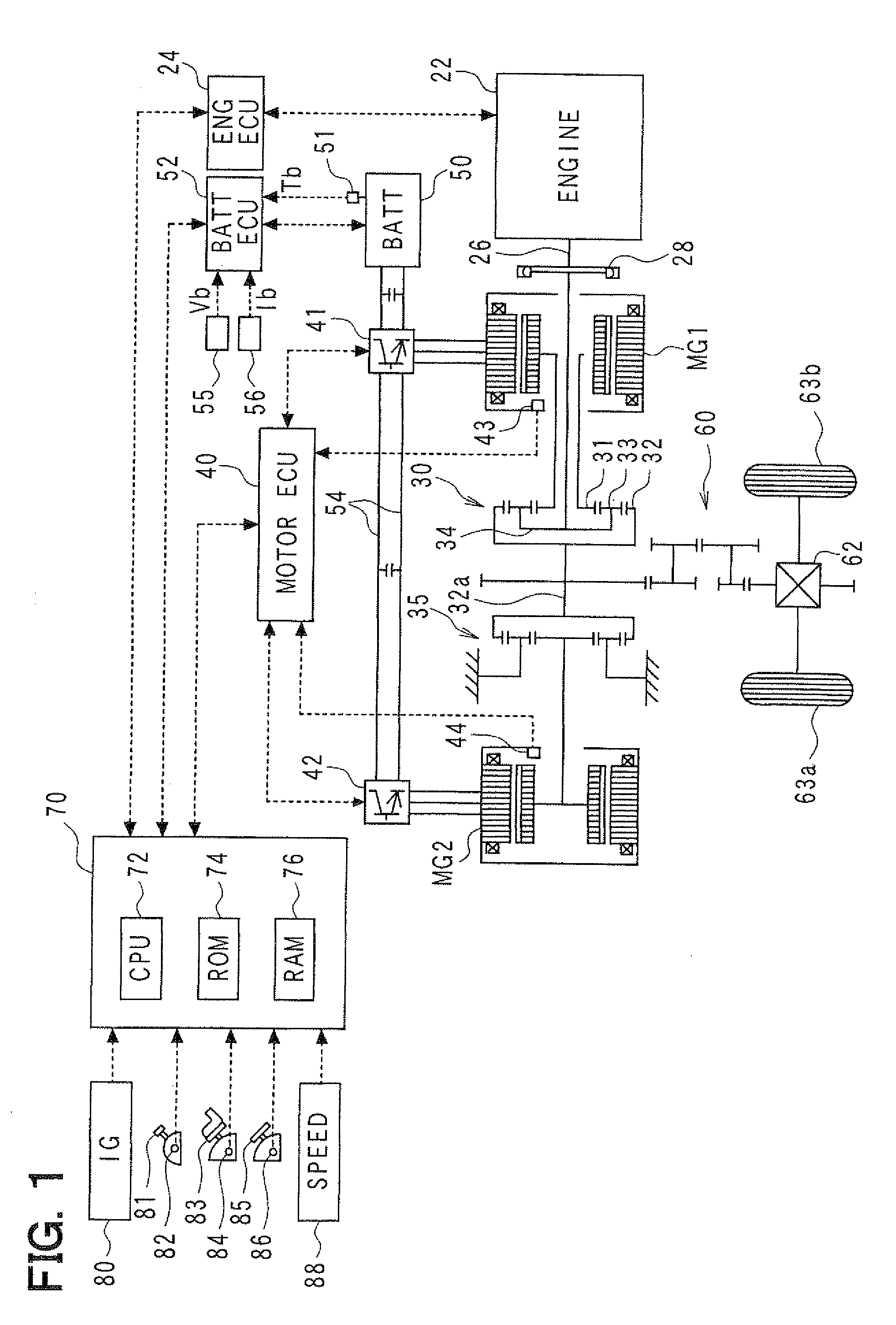
However, this normal current use range of the battery current may change according to the battery condition such as the SOC, battery temperature, the cooling capacity or the like, thereby inducing the battery current to surpass the allowable current range and causing the excessive heating that leads to the breakage and the like, even when the battery charge discharge power is restricted for limiting the battery voltage to be within the normal voltage use range (See FIG. 2).

Method used


Image

  • Method and apparatus for charge discharge power control
  • Method and apparatus for charge discharge power control
  • Method and apparatus for charge discharge power control

Examples


first embodiment

[0030]The first embodiment of the present disclosure is explained with reference to FIGS. 1 to 7.

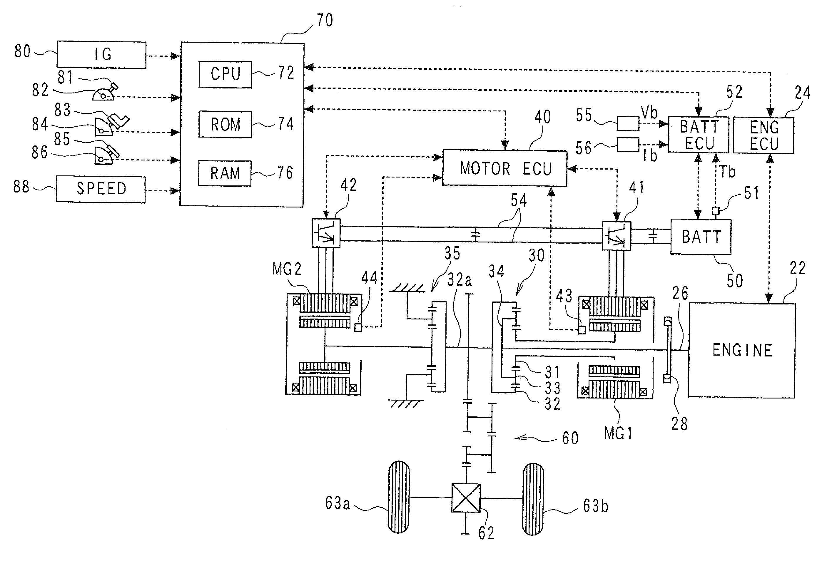
[0031]FIG. 1 is a block diagram of configuration of the hybrid electric vehicle. In the present embodiment, the hybrid electric vehicle includes an engine 22, a power division mechanism 30 having three axes in connection to a crank shaft 26 of the engine 22 through a dumper 28, a first motor MG 1 that serves as a generator if required in connection to the power division mechanism 30, a reduction gear 35 engaging with a ring gear axis 32a that is in connection to the power division mechanism 30, a second motor MG 2 that serves as a generator if required in connection to the reduction gear 35 and other parts. The above components are operated as a hybrid drive system under a total control of a hybrid ECU 70. The abbreviation “ECU” stands for an electronic control unit that employs, as a main part, a microcomputer for controlling the system circuitry.

[0032]The engine 22 is an internal combu...

second embodiment

[0084]In the above embodiment, the battery 50 is assumed to have an internal resistance that is inversely proportional to the battery temperature. In the present embodiment, the battery current and battery voltage are sampled at least two points, for the calculation of the inclination and intercept of the linear approximation. In the following description of the present embodiment, how to calculate the parameters (an inclination mb, and an intercept Vb.o) of the current-voltage characteristics equation based on the current / voltage samples detected by the current sensor 56 and the voltage sensor 55 for the calculation of the limit value is explained. The calculation of the limit value of the charge discharge power is possible in the above-described manner, because the inclination mb of the current-voltage characterisitics equation can be used as the internal resistance of the battery 50.

[0085]For example, the relation between the battery voltage Vb and battery electric current Ib is ...

third embodiment

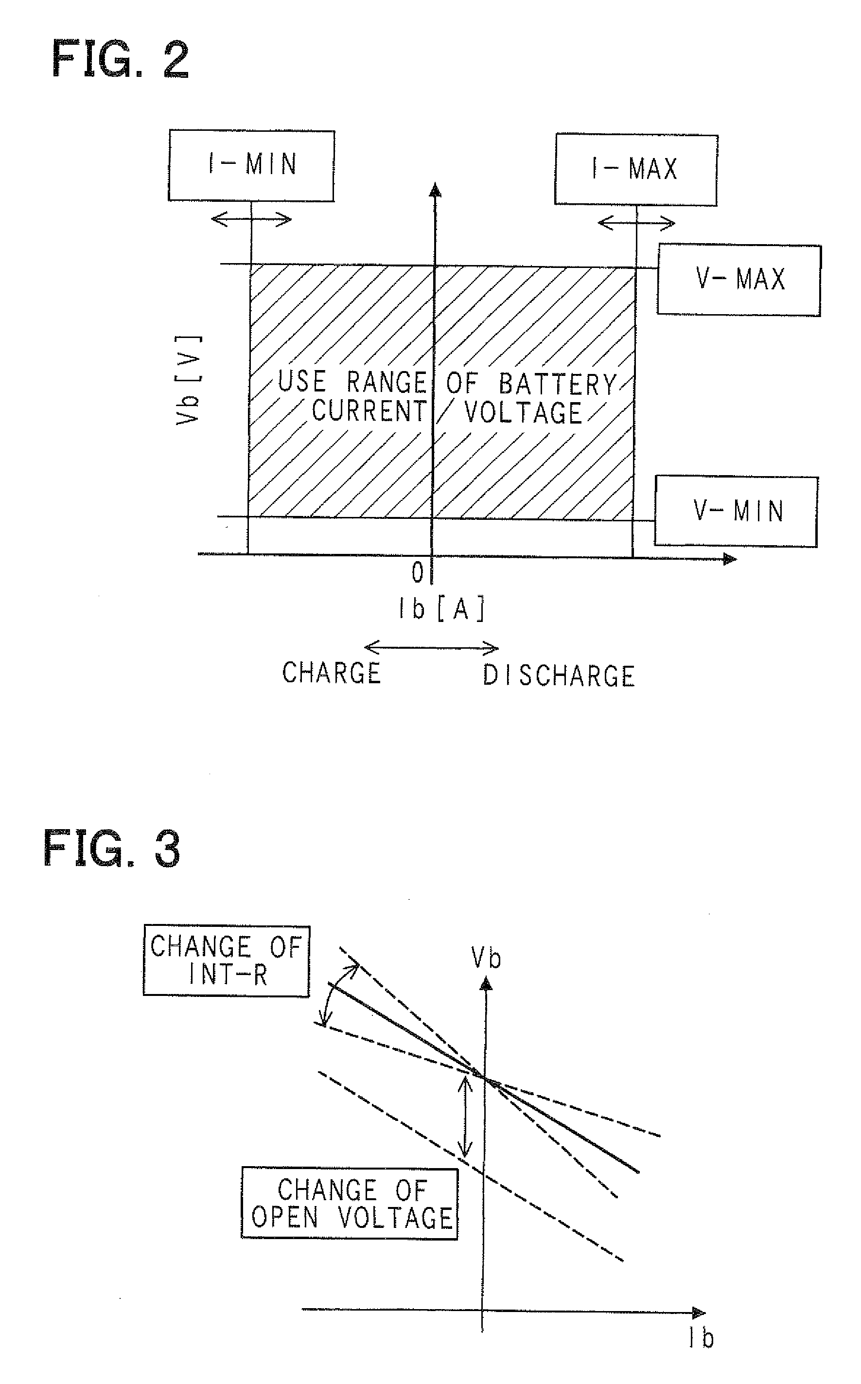
[0113]The actual current-voltage characteristics of the battery 50 is non-linear, due to the change of the open voltage Eo and the polarization voltage ηx. More specifically, as shown in FIGS. 10 and 11, the continuation of a large current, the amount of change of the open voltage Eo and the polarization voltage ηx increases. Therefore, the approximation of the current-voltage characteristics of the battery 50 may preferably be conducted by using a more complex model equation, in terms of achieving an improved accuracy of the current / voltage control. However, the complex model of the current-voltage characteristics demands increased process for the calculation of the parameters of the complex model.

[0114]Therefore, the difference between the maximum / minimum values of the current use range (Ib.max, Ib.min) and the detected current Ib.obs is calculated as a margin, and the difference between the maximum / minimum values of the voltage use range (Vb.max. Vb.min) and the detected voltage ...


PUM


Abstract

Limit values of battery charging and discharging power are set by a battery charge discharge control apparatus, based on the estimation of the internal resistance of a battery according to a detected battery temperature and the sampling of a battery current and a battery voltage respectively detected by a current sensor and a voltage sensor. The limit values are used to control the battery current and the battery voltage to be within a current use range and a voltage use range of the battery, according to conditions of the battery in a vehicle.

Description

CROSS REFERENCE TO RELATED APPLICATION[0001]The present application is based on and claims the benefit of priority of Japanese Patent Application No. 2008-252208, filed on Sep. 30, 2008, the disclosure of which is incorporated herein by reference.FIELD OF THE INVENTION[0002]The present invention generally relates to a charge discharge control apparatus for controlling charging and discharging of a battery (i.e., a secondary battery) for use in a vehicle.BACKGROUND INFORMATION[0003]In recent years, a battery charge discharge control apparatus controls, as disclosed in Japanese patent document Laid-Open No. 2007-306771 (on pages 1 to 5; also available as EP2019468A1), a battery charge and discharge power for limiting a battery voltage applied to a battery within a normal voltage use range (i.e., within an allowable voltage range).[0004]However, the battery (i.e., a secondary battery) may suffer an unintended internal composition change due to an abnormal chemical reaction when receivi...

Claims


Application Information

Patent Timeline
IPC IPC(8): H02J7/00
CPCH01M10/44H01M10/486Y02T10/7005H02J7/1453H02J7/14H02J7/007194Y02T10/70Y02E60/10
Inventor MASUDA, EIJI
Owner DENSO CORP
Learn More