Measurement of intracardiac impedance in a multisite-type, active implantable medical device, in particular a pacemaker, defibrillator and/or cardiovertor

a multi-site type, active technology, applied in the field of measuring intracardiac impedance in multi-site type, active implantable medical devices, can solve the problems of unrealizable practice, unreliable and precise measurement, and device use complex and multiple switching, etc., to achieve simple and advantageous system realization, the effect of reducing the additional circuitry

Inactive Publication Date: 2003-03-25
SORIN CRM
View PDF5 Cites 84 Cited by
  • Summary
  • Abstract
  • Description
  • Claims
  • Application Information

AI Technical Summary

Benefits of technology

It is, therefore, an object of the present invention to propose an improved configuration making it possible to adapt the minute-ventilation measuring circuitry to evaluate intracard

Problems solved by technology

In practice, however, it is noted that this configuration (a bipolar configuration of two electrodes) of injection/collection appears sensitive to the movement of the probes containing the electrodes, and does not allow a reliable and precise measurement of the impedance.
But this known device also uses complex and multiple switching,

Method used


Image

  • Measurement of intracardiac impedance in a multisite-type, active implantable medical device, in particular a pacemaker, defibrillator and/or cardiovertor
  • Measurement of intracardiac impedance in a multisite-type, active implantable medical device, in particular a pacemaker, defibrillator and/or cardiovertor
  • Measurement of intracardiac impedance in a multisite-type, active implantable medical device, in particular a pacemaker, defibrillator and/or cardiovertor

Examples


Embodiment Construction

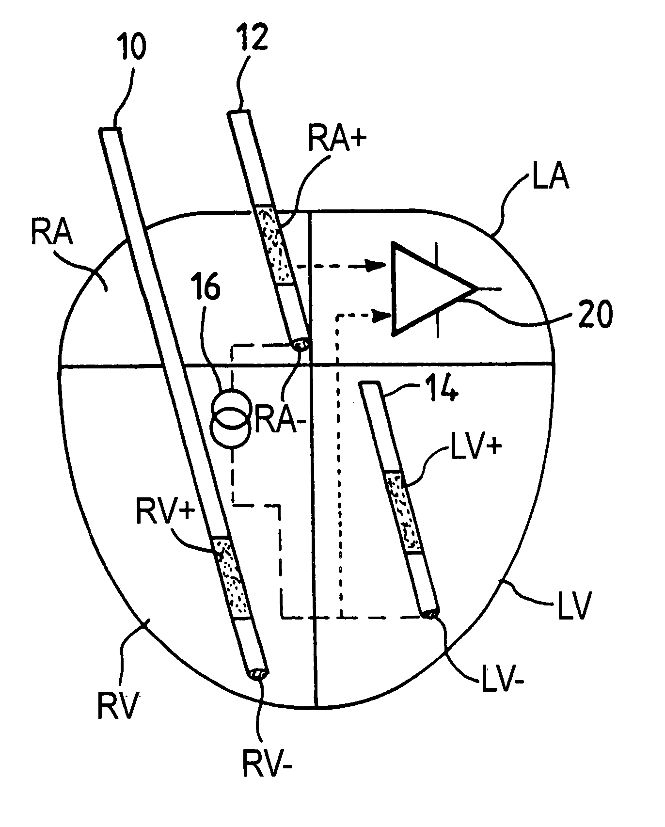
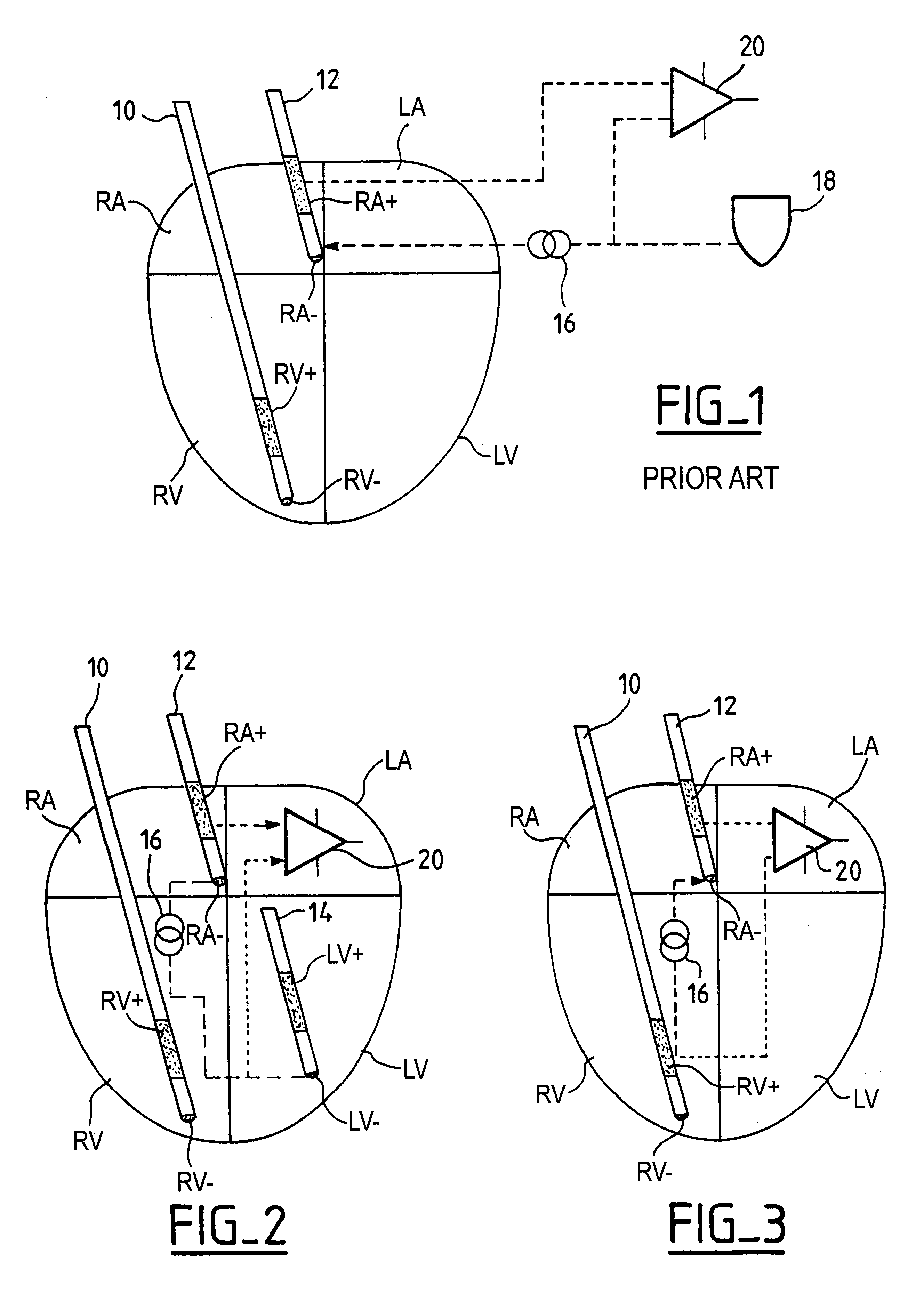
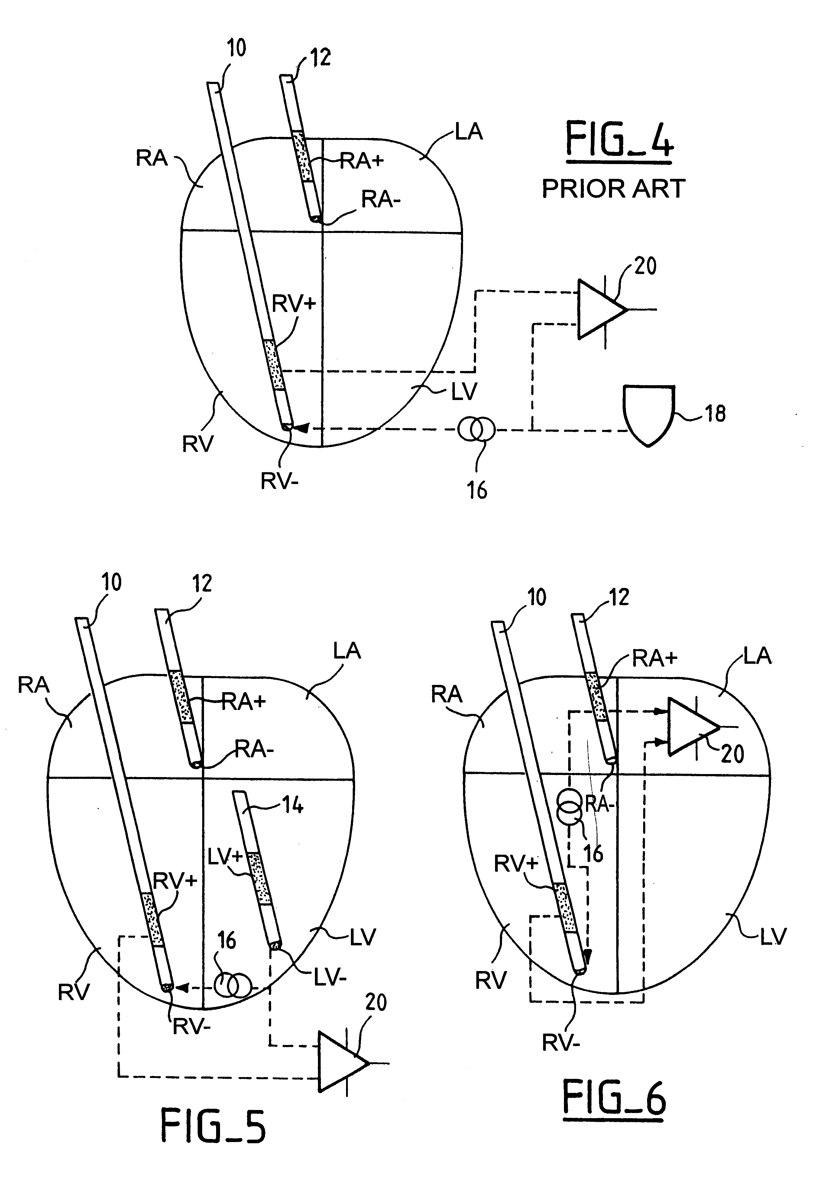
FIG. 1 schematically represents a cardiac muscle with its four cavities: right atrium RA, left atrium LA, right ventricle RV and left ventricle LV. A ventricular probe 10 is introduced into right ventricle RV, with an annular proximal electrode RV+ and a distal tip electrode RV-. An atrial probe 12 is introduced into right atrium RA, with a proximal annular electrode RA+ and a distal tip electrode RA-.

If necessary, it can also be envisaged (as shown in FIGS. 2 and 5) to include a probe 14 on the left ventricle LV, for example, to allow a biventricular stimulation (a triple chamber configuration) and / or a probe on the left atrium LA, if one wishes to carry out a collection of signals and / or a stimulation on the two atria in a quadruple chamber configuration.

The electrodes of the probes are connected to a case of an active implantable medical device which involves various detection, stimulation and control circuits, for example, a case of a multisite pacemaker such as that described i...


PUM


Abstract

An active implantable medical device, in particular a pacemaker, defibrillator or cardioveter of the multisite type, including a circuit for measuring intercardiac impedance. Electrodes are placed in at least one ventricular site and one atrial site, and are connected to a circuit for the collection of cardiac signals, to detect a depolarization potential, as well as to a stimulation circuit, to apply stimulation pluses to at least some of the aforementioned sites. The measurement of a trans-pulmonary bio-impedance is obtained by injecting a current from an injection circuit (16) between the case (18) of the device and a first atrial (RA-) (or ventricular) site, and measuring a differential potential (20) between the case (18) and a point of measurement located in a second atrial (RA+) (or ventricular) site using a collection circuit. Switches are selectively operable to isolate the case (18) from the current injection and measurement of potential circuits, and to connect them to a common reference potential site, atrial or ventricular (LV-), which is distinct from the sites (RA-,RA+) to which are also connected these circuits, so as to allow a measurement of intracardiac impedance from the signal delivered by the differential potential measuring circuit. The switching is obtained by connections to an electric ground, operating independently of the current injection circuit and the differential potential measuring circuit.

Description

The present invention relates to "active implantable medical devices" as such devices are defined by the Jun. 20, 1990 directive 90 / 385 / CEE of the Council of the European Cornmunities, more particularly to pacemaker, defibrillator and / or cardiovertor devices that are able to deliver to the heart stimulation pulses of low energy for the treatment of heartbeat rate disorders. The invention is more particularly directed to the prostheses known as "multisite", in which respective electrodes are placed in a plurality of distinct respective cardiac sites comprising at least one ventricular site and one atrial site. This prosthesis can be of the "double chamber" (right atrial stimulation and right ventricular stimulation) or, generally, "triple chamber" (right atrial stimulation and double ventricular stimulation) or "quadruple chamber" (double atrial stimulation and double ventricular stimulation) type.The control of stimulation implies making an adjustment of various control parameters, ...

Claims


Application Information

Patent Timeline
IPC IPC(8): A61N1/368A61N1/365
CPCA61N1/368A61N1/36521
Inventor DAL MOLIN, RENZO
Owner SORIN CRM
Why Eureka
Try Eureka