Automatic engine control device

a technology of control device and engine, which is applied in the direction of engine starter, electric control, instruments, etc., can solve the problems of reducing the terminal voltage of the battery, reducing the capacity of the on-vehicle battery, and affecting the starting of the internal combustion engine. , to achieve the effect of preventing the voltage of the battery and high accuracy

Active Publication Date: 2010-10-28
DENSO CORP
View PDF8 Cites 74 Cited by
  • Summary
  • Abstract
  • Description
  • Claims
  • Application Information

AI Technical Summary

Benefits of technology

[0025]According to the sixth aspect of the present invention, the automatic engine control device judges the permission to perform the automatic engine stop based on the minimum voltage of the battery during the period until the next restart of the engine after the automatic engine stop. This minimum voltage of the battery is calculated based on the maximum discharging curren

Problems solved by technology

Such a large amount of current drastically decreases the terminal voltage of the battery, that is, reduces a large amount of capacity of the on-vehicle battery.
As a result, it is difficult for the on-vehicle battery to

Method used


Image

  • Automatic engine control device
  • Automatic engine control device
  • Automatic engine control device

Examples


first embodiment

[0049]A description will be given of an automatic engine control device according to a first embodiment of the present invention with reference to FIG. 1.

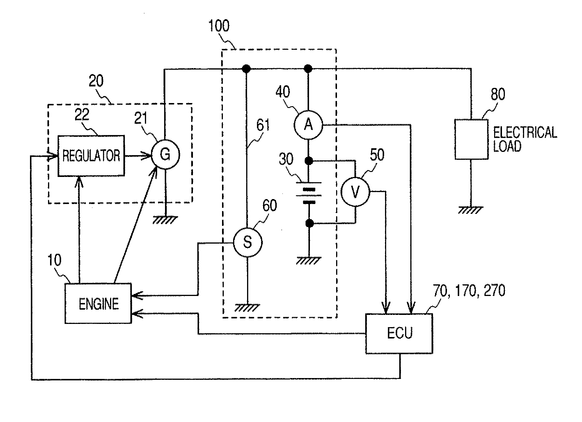
[0050]FIG. 1 is a block diagram showing an entire system structure of an automatic engine control device according to the present invention.

[0051]As shown in FIG. 1, the automatic engine control device has an internal combustion engine 10 (which will be referred to as the “engine 10”), an electric power generation device 20, a battery 30 such as a secondary battery, a current sensor 40, a voltage sensor 50, a starter 60 such as a starter motor, an engine control unit (ECU) 70, one or more electrical loads 80. FIG. 1 shows one electrical load 80 for brevity.

[0052]The engine 10 is mounted on a vehicle to serve as a driving power generator capable of supplying a driving torque to wheels of the vehicle and the electric power generation device 20. The electric power generation device 20 is comprised of an AC generator 21 and a regulator...

second embodiment

[0134]A description will be given of the automatic engine control device according to the second embodiment with reference to FIG. 11.

[0135]FIG. 11 is a view showing a map to be used by the battery state change detection part 71 in the ECU 70. This map shows a relationship between a time-integrated value ΔAh of a charge / discharge current of the battery 30 and the internal resistance value Rb of the battery 30 according to the second embodiment of the present invention.

[0136]By the way, the battery state change detection part 71 in the ECU 70 of the automatic engine control device according to the first embodiment detects the change of SOC and the change of temperature of the battery 30. The minimum voltage predicting part 72 calculates the internal resistance value Rb2 of the battery 30 at the present time based on the change of the SOC and the change of the temperature of the battery 30.

[0137]As shown in FIG. 11, the internal resistance value Rb of the battery is changed according ...

third embodiment

[0140]A description will be given of the automatic engine control device according to the third embodiment of the present invention with reference to FIG. 12.

[0141]FIG. 12 is a view showing a relationship between a voltage and a current of the battery 30 during the cranking period according to the third embodiment of the present invention.

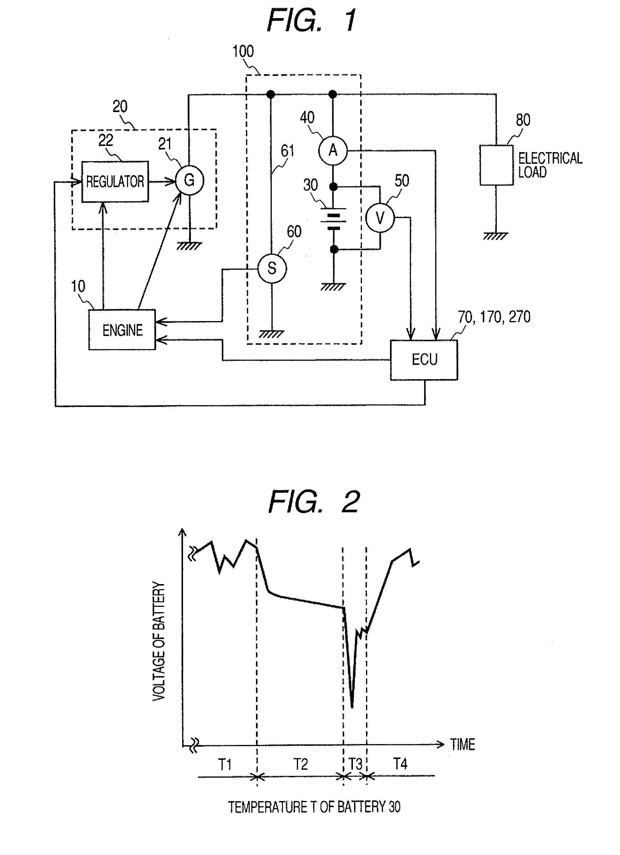
[0142]The first embodiment uses the premise that the automatic engine control device is able to detect the voltage Vstart1 of the battery 30 at the time immediately after the engine 10 starts, that is, at the timing to start the period Ta shown in FIG. 6A. In addition, the first embodiment uses another premise that the automatic engine control device detects the minimum voltage Vbtm1 of the battery 30 immediately after the initial start of the engine.

[0143]However, there is a case where the starter 60 drives the engine 10 before the ECU 70 reaches a stable state in operation when the vehicle driver turns on the ignition key of the vehicle in order ...


PUM


Abstract

An ECU in an automatic engine control device predicts a maximum discharging current to be supplied from a battery to a starter during a next restart of the engine based on a present voltage, an internal resistance value of the battery, and a starter total resistance value during automatic engine stop. The ECU further predicts a minimum voltage of the battery during a period until the next restart of the engine based on the present voltage, the present internal resistance value of the battery, and the predicted maximum discharging current. The ECU judges whether or not execution of the next restart of the engine during the automatic engine stop based on the predicted minimum voltage of the battery.

Description

CROSS-REFERENCE TO RELATED APPLICATION[0001]This application is related to and claims priority from Japanese Patent Applications No. 2009-105488 filed on Apr. 23, 2009, and No. 2010-8318 filed on Jan. 18, 2010, the contents of which are hereby incorporated by reference.BACKGROUND OF THE INVENTION[0002]1. Field of the Invention[0003]The present invention relates to automatic engine control devices capable of controlling an automatic engine stop of an internal combustion engine.[0004]2. Description of the Related Art[0005]Recently, some types of vehicles are equipped with an automatic engine control device. The automatic engine control device controls an automatic engine stop in order to stop an internal combustion engine during an idle state of the engine mounted to the vehicle. The execution of the automatic engine stop decreases a terminal voltage of an on-vehicle battery of the vehicle. Specifically, at the moment when the automatic engine control device switches the state of the ...

Claims


Application Information

Patent Timeline
IPC IPC(8): F02N11/08
CPCF02D29/06F02D41/042F02N11/0825Y02T10/48F02N2200/063F02N2300/2006G01R31/3662F02N2200/044G01R31/389Y02T10/40
Inventor MIZUNO, SATORU
Owner DENSO CORP
Why Eureka
Try Eureka