Electrical storage system

Active Publication Date: 2015-05-14
TOYOTA JIDOSHA KK
View PDF4 Cites 18 Cited by
  • Summary
  • Abstract
  • Description
  • Claims
  • Application Information

AI Technical Summary

Benefits of technology

[0011]In the aspect of the present invention, the inlet is connected to the electrical storage device via the second charging line, the first charging line and the electrode line. That is, the inlet is connected to the electrical storage device in the order of the second charging line, the first charging line and the electrode line. Herein, when the first charging relay provided on

Problems solved by technology

Therefore, a contacting portion between the movable contact a

Method used


Image

  • Electrical storage system
  • Electrical storage system
  • Electrical storage system

Examples


Example

[0025]Embodiments of the present invention is described below.

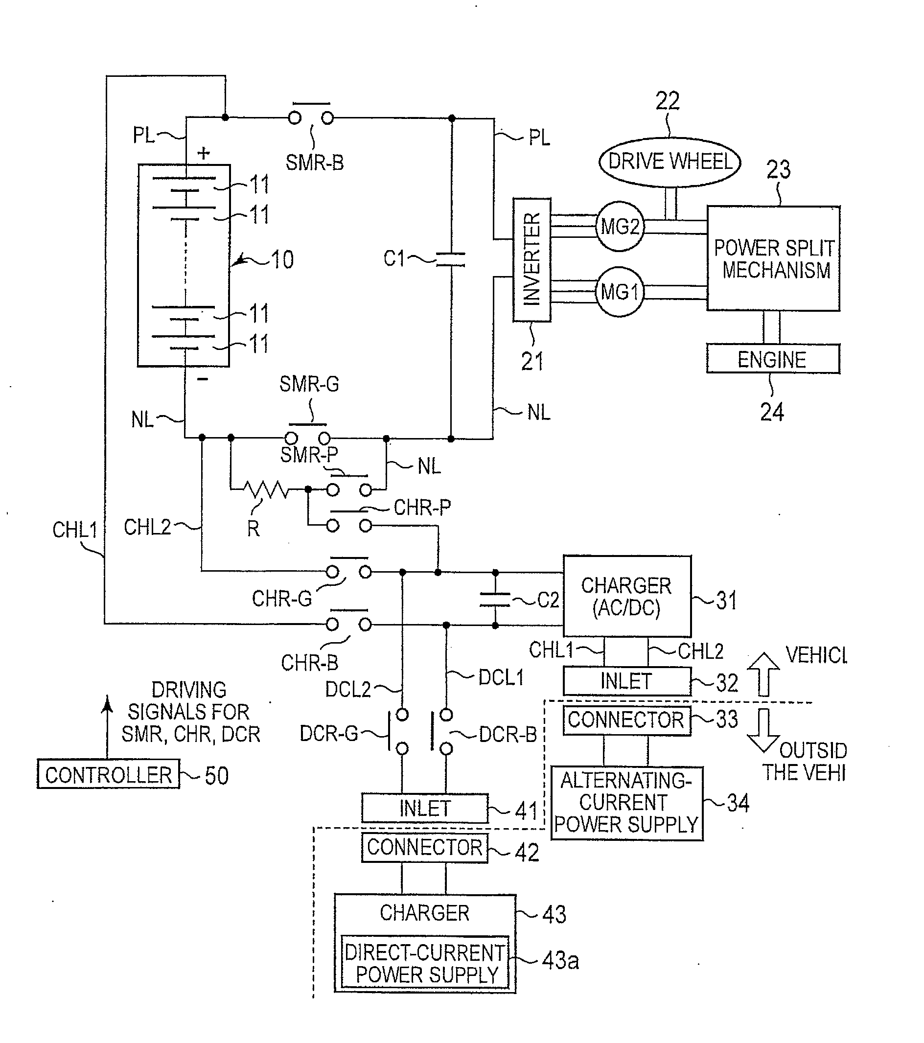
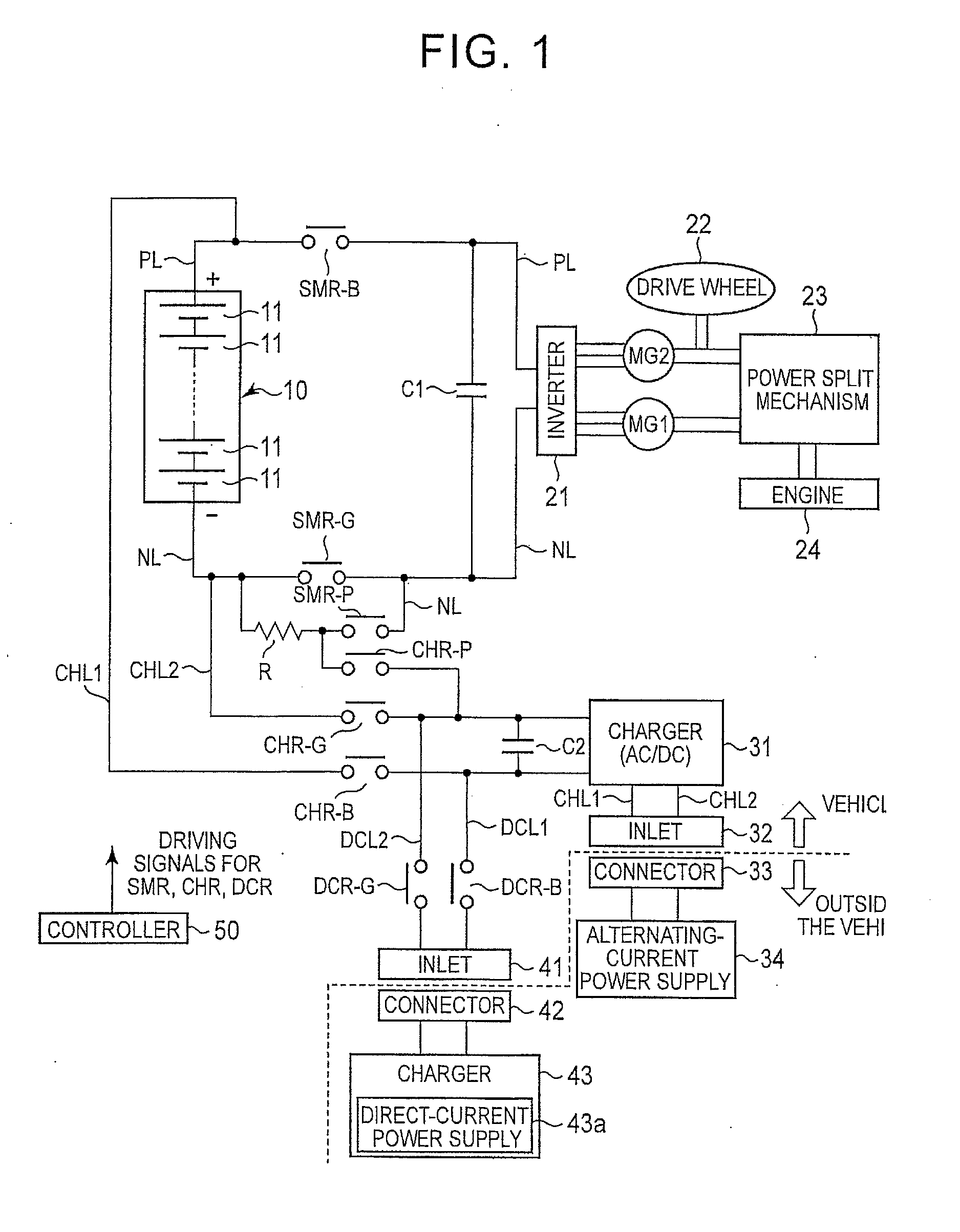
[0026]FIG. 1 is a diagram showing a configuration of a battery system (corresponding to an electrical storage system of the present invention) of the present embodiment. The battery system shown in FIG. 1 is carried on a vehicle.

[0027]A battery pack (corresponding to an electrical storage device of the present invention) 10 has a plurality of single cells 11 connected in series. A secondary battery such as a nickel-hydride battery and / or a lithium ion battery may be used as the single cell 11. Additionally, an electric double layer capacitor may also be used instead of the secondary battery. In the battery pack 10 of the present embodiment, all single cells 11 are connected in series, however, the battery pack 10 may also include a plurality of single cells 11 connected in parallel.

[0028]A positive electrode line (corresponding to an electrode line of the present invention) PL is connected to a positive electrode terminal...


PUM


Abstract

The electrical storage system includes an electrical storage device, a motor, a system main relay, a first charging line, a charger, a first charging relay, a second charging line, an inlet, a second charging relay and a controller. The controller is configured to control a energizing state and a non-energizing state of the system main relay, the first charging relay and the second charging relay. The controller is configured to cause the first charging relay to the non-energizing state when the second charging relay in the energizing state is subjected to adhesion.

Description

INCORPORATION BY REFERENCE[0001]The disclosure of Japanese Patent Application No. 2013-232567 filed on Nov. 8, 2013 including the specification, drawings and abstract is incorporated herein by reference in its entirety.BACKGROUND OF THE INVENTION[0002]1. Field of the Invention[0003]The invention relates to an electrical storage system capable of charging an electrical storage device using a direct-current (DC) power supply and an alternating-current (AC) power supply.[0004]2. Description of Related Art[0005]In Japanese Patent Application Publication No. 2012-228060 (JP 2012-228060 A), a system for charging a battery for traveling using a DC power supply is disclosed. In the system, a main contactor (so-called relay) is provided on a main power line connecting the battery for traveling with an inverter. By allowing the main contactor to be turned on, electric power can be supplied to the inverter from the battery for traveling, to enable a vehicle to travel.[0006]In the system disclo...

Claims


Application Information

Patent Timeline
IPC IPC(8): B60L11/18H02J7/00B60K6/22B60K6/445B60L3/00B60L50/16
CPCH02J7/007B60L11/1812B60L53/22H02J2207/40H02J7/0029H02J7/02Y02T10/7072Y02T90/14B60L3/0069B60L3/04B60L53/14B60L53/20H02J2310/48Y02T10/70H02J7/00304H02J5/00H02J50/10
Inventor IZUMI, JUNTA
Owner TOYOTA JIDOSHA KK
Why Eureka
Try Eureka