Electronic control apparatus having switching element and drive circuit

a technology of switching element and drive circuit, which is applied in the direction of electronic switching, control system, pulse technique, etc., can solve the problems of control circuit detecting abnormality of the constant-current circuit of the on-drive power transistor, power transistor damage by excessive heat, and power transistor damage, so as to prevent the effect of thermal fracture of the switching elemen

Active Publication Date: 2012-07-26
DENSO CORP
View PDF8 Cites 18 Cited by
  • Summary
  • Abstract
  • Description
  • Claims
  • Application Information

AI Technical Summary

Benefits of technology

[0024]According to this configuration, even when the ON-drive constant-current circuit is faulty, the voltage between the input terminal and the output terminal of the current control transistor becoming unstable can be avoided. Therefore, abnormality of the ON-drive constant-current circuit can be reliably detected based on the voltage of the current control transistor.
[0030]According to this configuration, the current detection resistor is connected to the current control transistor. Therefore, the wiring from the current detection resistor to the current control circuit, and the wiring from the current control transistor to the abnormality detection circuit can be partly shared. However, both wirings are provided separately without sharing the wirings. As a result, even if the wiring between the current detection resistor and the current control circuit is broken, the control circuit can detect abnormality of the ON-drive constant-current circuit.
[0032]According to the configuration, thermal fracture of the switching element accompanying the abnormality in the ON-drive constant-current circuit can be prevented.
[0034]According to the configuration, when an abnormality is detected in the ON-drive constant-current circuit, the switching element is turned OFF by the OFF-holding switching element being controlled and electrical charge being discharged from the control terminal of the switching element. Therefore, thermal fracture of the switching element can be prevented.

Problems solved by technology

In the above-described motor drive unit, when the first current source is in a faulty condition, the gate voltage of the power transistor does not decrease so that an abnormal condition where the power transistor cannot be turned OFF may occur.
Therefore, if such an abnormal condition continues, the power transistor may be damaged by excessive heat.
However, when the OFF-drive switching element has a short-circuit fault or the OFF-drive switching element is turned ON due to a fault of a control portion in the control circuit that controls the OFF-drive switching element, the voltage between the input terminal and the output terminal of the current control transistor becomes greater than a predetermined threshold voltage.
However, when the current control transistor has a short-circuit fault or the current control transistor is turned ON due to a fault of a control portion in the control circuit that controls the current control transistor, the voltage between the input terminal and the output terminal of the current control transistor becomes smaller than the voltage when the constant-current is not supplied to the control terminal.
As a result, even if the wiring between the current detection resistor and the current control circuit is broken, the control circuit can detect abnormality of the ON-drive constant-current circuit.

Method used


Image

  • Electronic control apparatus having switching element and drive circuit
  • Electronic control apparatus having switching element and drive circuit
  • Electronic control apparatus having switching element and drive circuit

Examples


Embodiment Construction

[0042]Hereinafter will be described an embodiment of the present invention. According to the embodiment, the electronic control apparatus of the present invention is adapted to an on-vehicle motor control device that controls vehicle-drive motor.

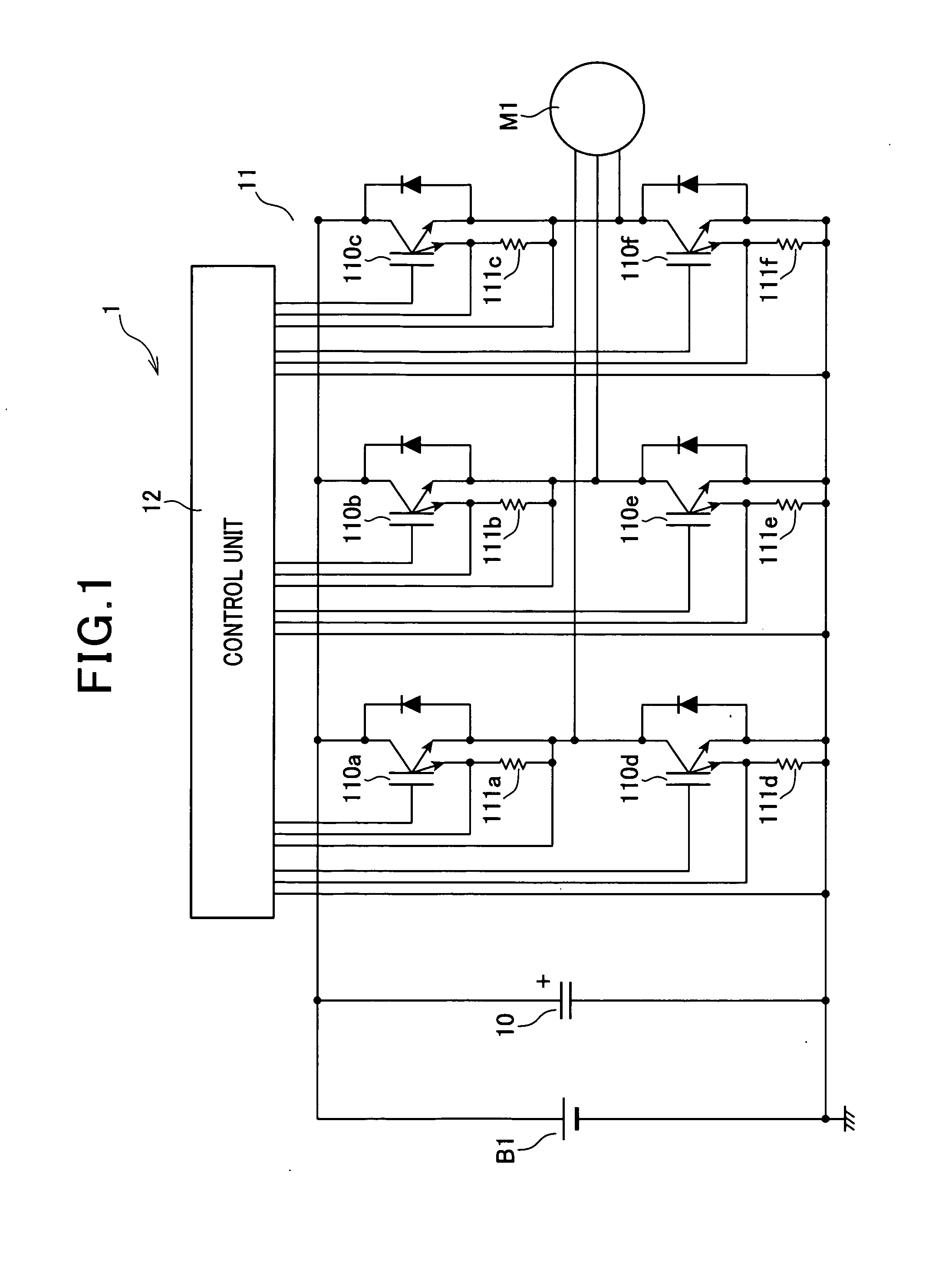
[0043]With reference to FIG. 1, the motor control device according to the embodiment is described as follows. FIG. 1 is a circuit diagram showing the motor control device according to the embodiment.

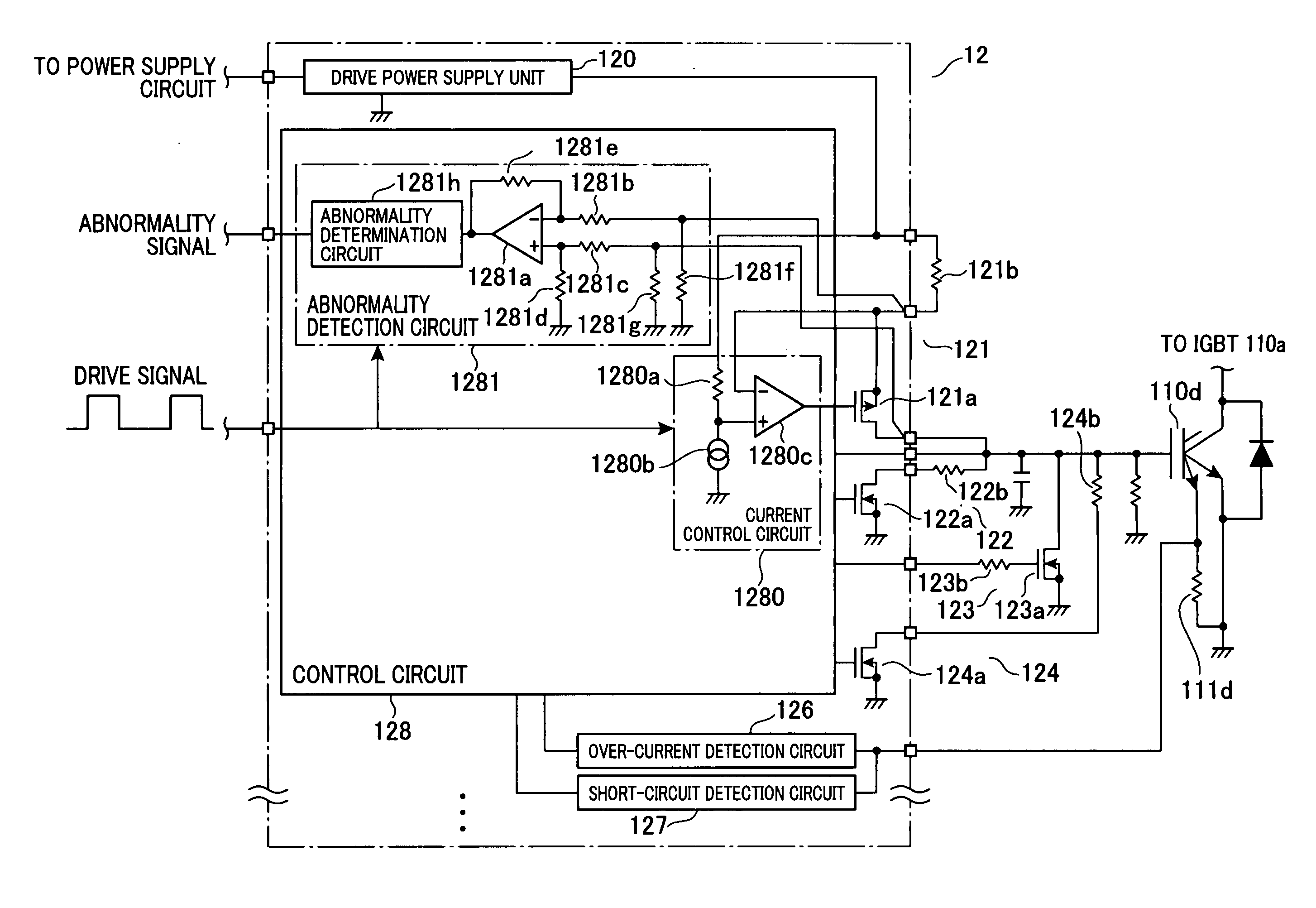
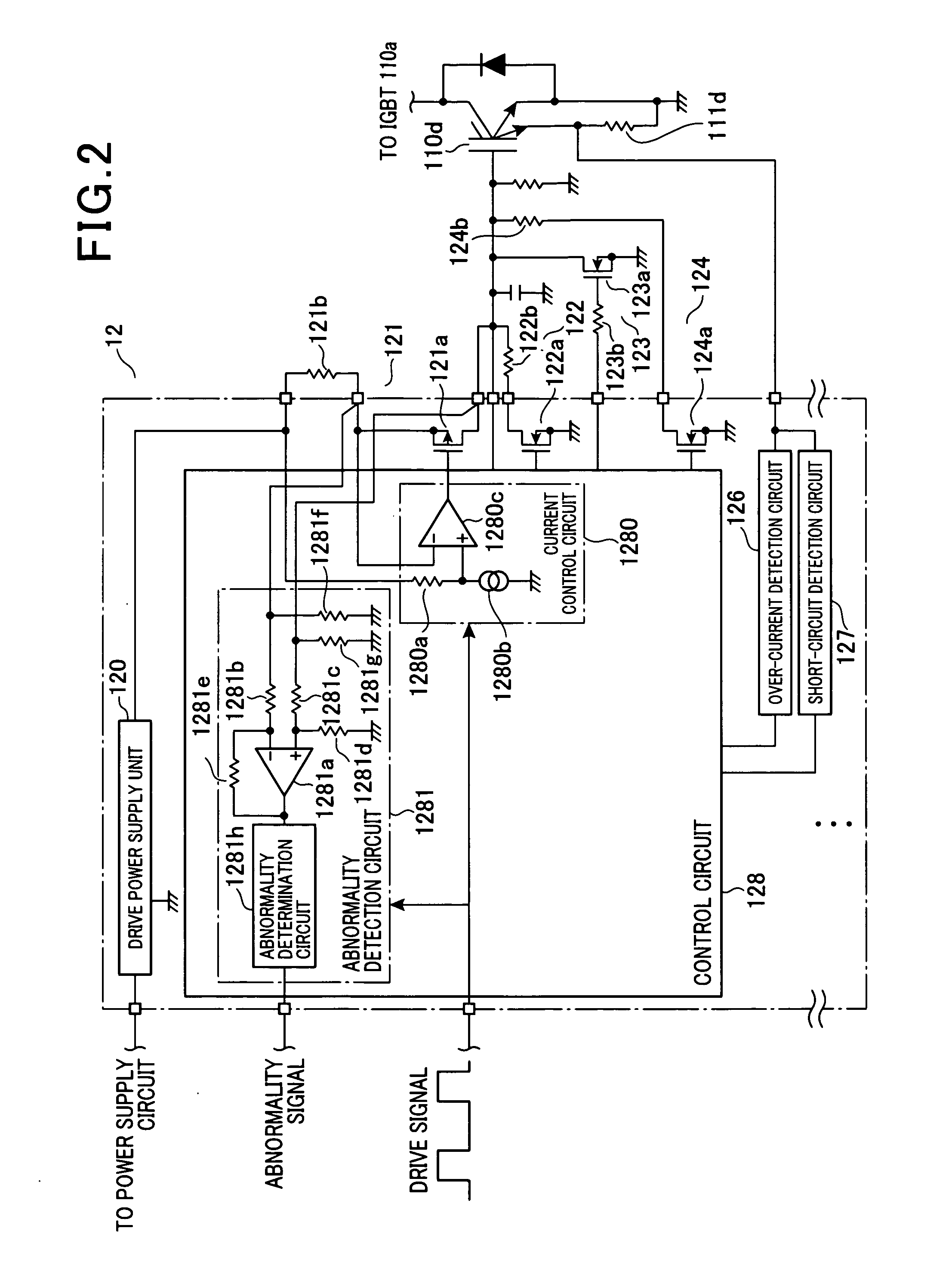
[0044]The motor control device 1 as shown in FIG. 1 (electronic control apparatus) is adapted to control a vehicle-drive-motor M1 such that the motor control device 1 converts DC (direct current) high voltage (e.g. 288 volts) outputted by a high voltage battery B1 which is isolated from the vehicle-body into three phase AC (alternate current) voltage and supplies the converted AC voltage to the vehicle-drive-motor Ml. The vehicle-drive-motor M1 includes a smoothing capacitor 10, an inverter unit 11 and a control unit 12.

[0045]The smoothing capaci...


PUM


Abstract

An electronic control apparatus includes a switching element having a control terminal; an ON-drive constant-current circuit for supplying a constant current to the control terminal, thereby charging the control terminal of the switching element with electrical charge; an OFF-drive switching element for discharging electrical charge from the control terminal of the switching element by being turned ON; and a control circuit adapted to control the ON-drive constant-current circuit and the OFF-drive switching element in response to a drive signal being inputted, thereby controlling the voltage of the control terminal of the switching element to drive the switching element. The ON-drive constant-current circuit includes a current control transistor and a current detection element. The control circuit controls the current control transistor based on the voltage of the current detection resistor and detects abnormality in the ON-drive constant-current circuit based on a source-drain voltage of the current control transistor.

Description

CROSS REFERENCE TO RELATED APPLICATION[0001]This application is based on and claims the benefit of priority from earlier Japanese Patent Application No. 2011-13248 filed on Jan. 25, 2011 the description of which is incorporated herein by reference.BACKGROUND[0002]1. Technical Field[0003]The present application relates to an electronic control apparatus having a switching element and a drive circuit, and more particularly to an electronic control apparatus used for driving motors and capable of detecting faults of the drive circuit.[0004]2. Description of the Related Art[0005]Conventionally, an electronic control apparatus having a switching element and a drive circuit have been employed. For example, Japanese Patent Application Laid-Open Publication No. 2007-288856 discloses a motor drive unit as an electronic control apparatus.[0006]The motor drive unit disclosed in the above patent document includes a power transistor and a gate driver. The gate driver includes first and second cu...

Claims


Application Information

Patent Timeline
Patent Type & Authority Applications(United States)
IPC IPC(8): H03K17/687
CPCH02P29/02H03K17/0828H03K17/08128
Inventor MIZOBE, SHUNICHIMAEBARA, TSUNEOWATANABE, KAZUNORI
Owner DENSO CORP
Why Eureka
Try Eureka