

Monitor circuit for a current limiting device
Inactive Publication Date: 2002-12-10
ABB RES LTD
View PDF9 Cites 18 Cited by
- Summary
- Abstract
- Description
- Claims
- Application Information
AI Technical Summary
Benefits of technology
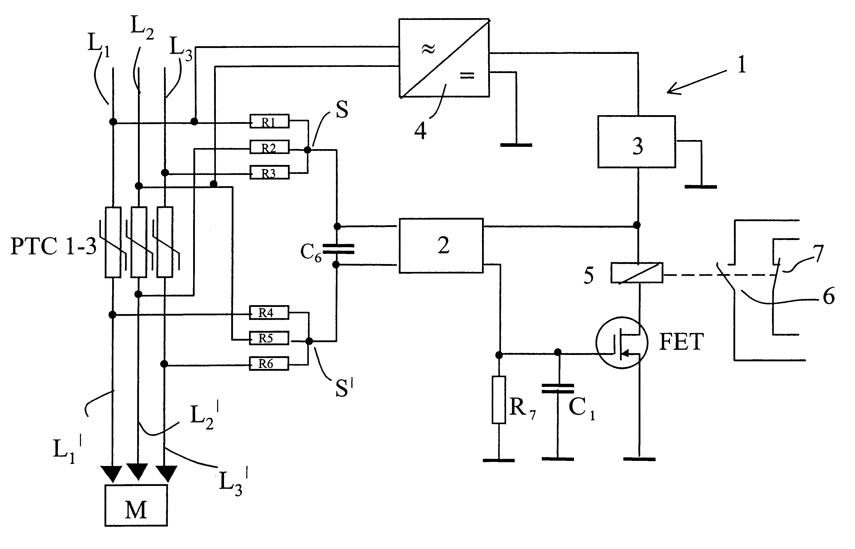
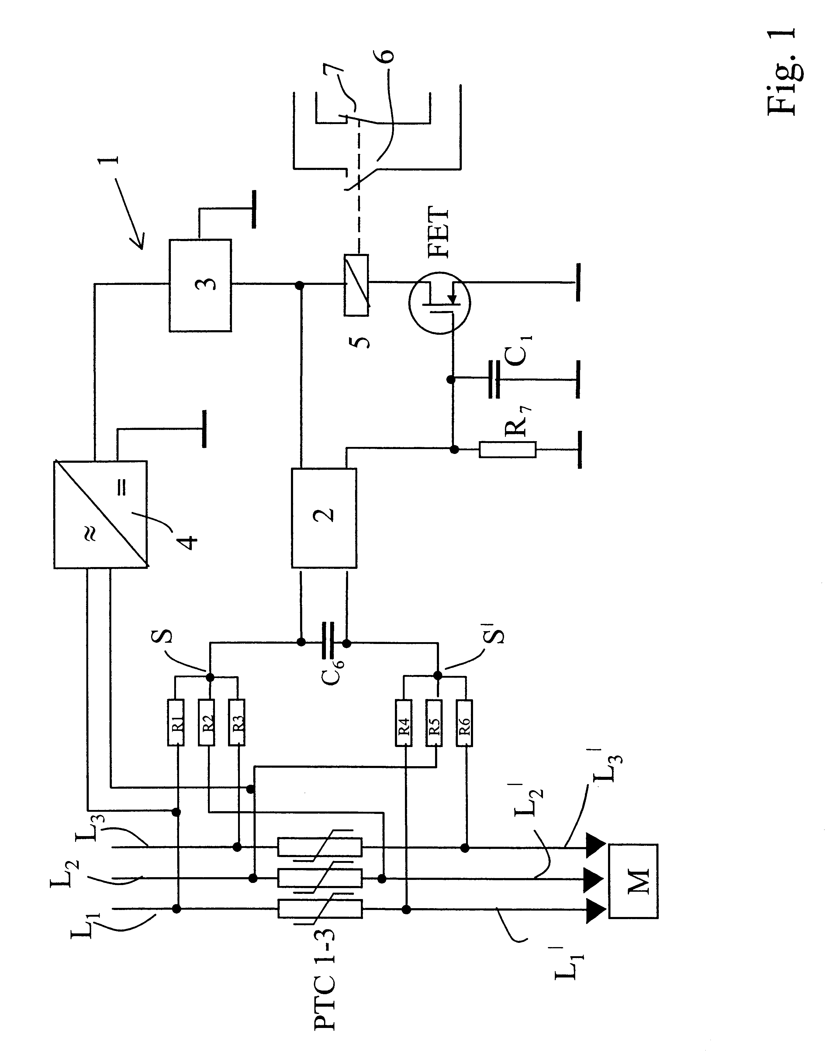
According to the invention, one star point is a combination of two taps of one side and one tap of the other side of said three-phase current limiting device, the other star point being a combination of the remaining three taps, again two on the latter and one on the former side. The advantage of the circuit design is that the monitor circuit is responsive equally to triggering of anyone, any two or all three single phase current limiting means and that the circuit design is remarkably simple.
This applies especially to a preferred application of the invention in a circuit for power supplying and protecting an electrical motor. A three-phase motor can be destroyed if operated by only one or two phases. Therefore, the invention provides an important advantage over the mere application of independent single-phase current limiting devices in motor circuits.
In order to prevent a triggering of the voltage detector by very short disturbances and noise in the three-phase line that do not lead to a limiting effect of the current limiting device, it is also effective to provide for an another capacitor, additionally or alternatively, between both star points. Also the charging delay time of this capacitor can provide for a voltage buildup between the star points over said time period and thus for said time continued detection by the voltage detector.
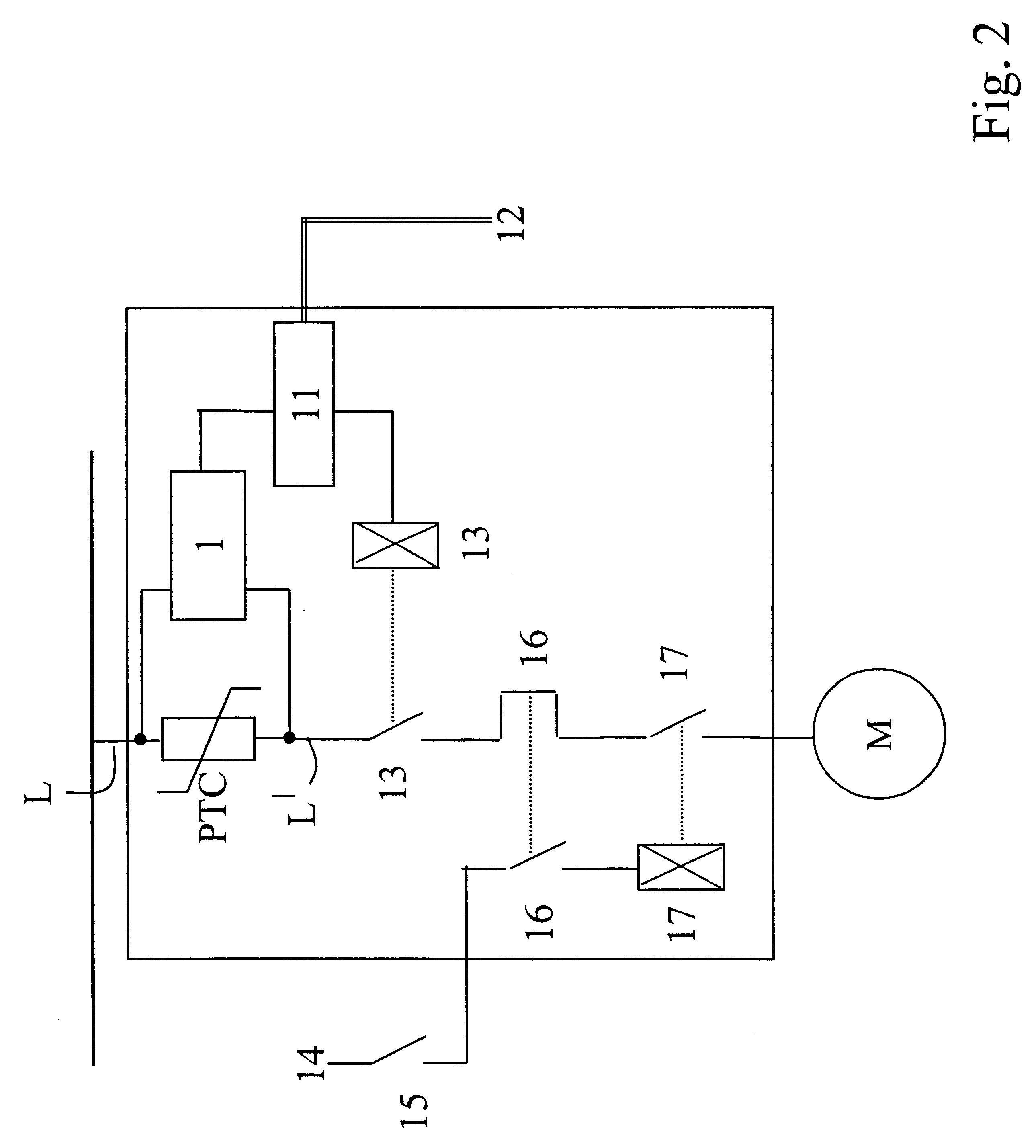
So far, the term "current limiting device" has been used in its generality in order to demonstrate that the invention works with the variety of special embodiments for this device. However, the most common and commercially important embodiment is a set of three thermal fuses, each for one phase. A fuse is in fact more than a current limiting device, actually a current interrupting device. However, this is not essential for the invention. Accordingly, in this application the term current limiting also includes a limitation to zero. In case of thermal fuses, it is preferred to open at least one three-phase switch at a high voltage side of the fuses, more preferably two three-phase switches, each on one side of the fuses, it can be guaranteed by opening the switch(es) that the contacts in which the fuses are mounted and in which a replacement has to be effected, are free of any harmful potential.
Problems solved by technology
However, they do not really provide for a galvanic interruption of the current as a thermal fuse does.
On the other hand, if the high voltage across the PTC resistor is present over said time period, it can be concluded, that a serious fault has been detected leading to an opening of the switch.
Method used
View moreImage
Smart ImageViewing Examples

Examples
first embodiment
FIG. 2 shows a schematic circuit diagram of a motor power supplying and protecting circuit including the invention ;
second embodiment
FIG. 3 shows a schematic circuit diagram of a motor power supplying and protecting circuit including the invention ;
third embodiment
FIG. 4 shows a schematic circuit diagram of a motor power supplying and protecting circuit including the invention ; and
Login to View More PUM
 Abstract
An electrical monitor circuit in which star points of taps on a first and a second side of a three-phase current limiting device are voltage compared. Possible applications are combinations with electrical switches, especially for power supplying and protecting circuits for electrical motors.
Description
This invention relates to an electrical monitor circuit for monitoring a status of a three-phase current limiting device. The current limiting device is intended to limit or interrupt a current in a three-phase line. Consequently, the current limiting device comprises three one-phase current limiting means, one for each one-phase line.The monitor circuit according to the invention is intended to monitor whether the current limiting device is in its normal conducting, i.e. relatively low resistance status or whether there is any current limiting or current interrupting effect of the current limiting device present.RELATED ARTA prior art solution concerning monitoring of a current limiting device is shown in DE 43 40 632 A1. Therein, the voltage across a PTC resistor being connected in series with a load break switch is used to trigger the opening of the load break switch. The PTC resistor is intended to improve the current limiting capability of the load break switch which finally in...
Claims
Login to View More Application Information
Patent Timeline
 IPC IPC(8): H02H3/02H02H3/04H02H9/02
CPCH02H3/046H02H9/026
InventorRAJALA, ERKKISTRUMPLER, RALFJOKINIEMI, TIMO
OwnerABB RES LTD