
Waveform calibration method and device

A calibration method and a technology of a calibration device, which are applied in the direction of measuring devices, instruments, and measuring electrical variables, etc., can solve problems such as unposedness of the calibration process, inaccurate waveform calibration, etc., and achieve the effect of solving the unwell problem of waveform calibration

Active Publication Date: 2018-12-11
BEIJING INST OF RADIO METROLOGY & MEASUREMENT
View PDF5 Cites 0 Cited by
  • Summary
  • Abstract
  • Description
  • Claims
  • Application Information

AI Technical Summary

Problems solved by technology

[0003] The present invention provides a waveform calibration method and device, which solves the problems of inaccurate waveform calibration and ill-posed calibration process in existing methods and devices

Method used


Image

  • Waveform calibration method and device
  • Waveform calibration method and device
  • Waveform calibration method and device

Examples


Embodiment Construction

[0025] In order to make the purpose, technical solution and advantages of the present invention clearer, the technical solution of the present invention will be clearly and completely described below in conjunction with specific embodiments of the present invention and corresponding drawings. Apparently, the described embodiments are only some of the embodiments of the present invention, but not all of them. Based on the embodiments of the present invention, all other embodiments obtained by persons of ordinary skill in the art without making creative efforts belong to the protection scope of the present invention.

[0026] Since the 1960s, in many fields of science and technology, such as signal processing, remote sensing technology, pattern recognition, physical and life science, material science, fluid mechanics, industrial control and even economic decision-making, the principle of "inverting input from output" has been proposed. Problems, commonly known as "mathematical a...


PUM


Abstract

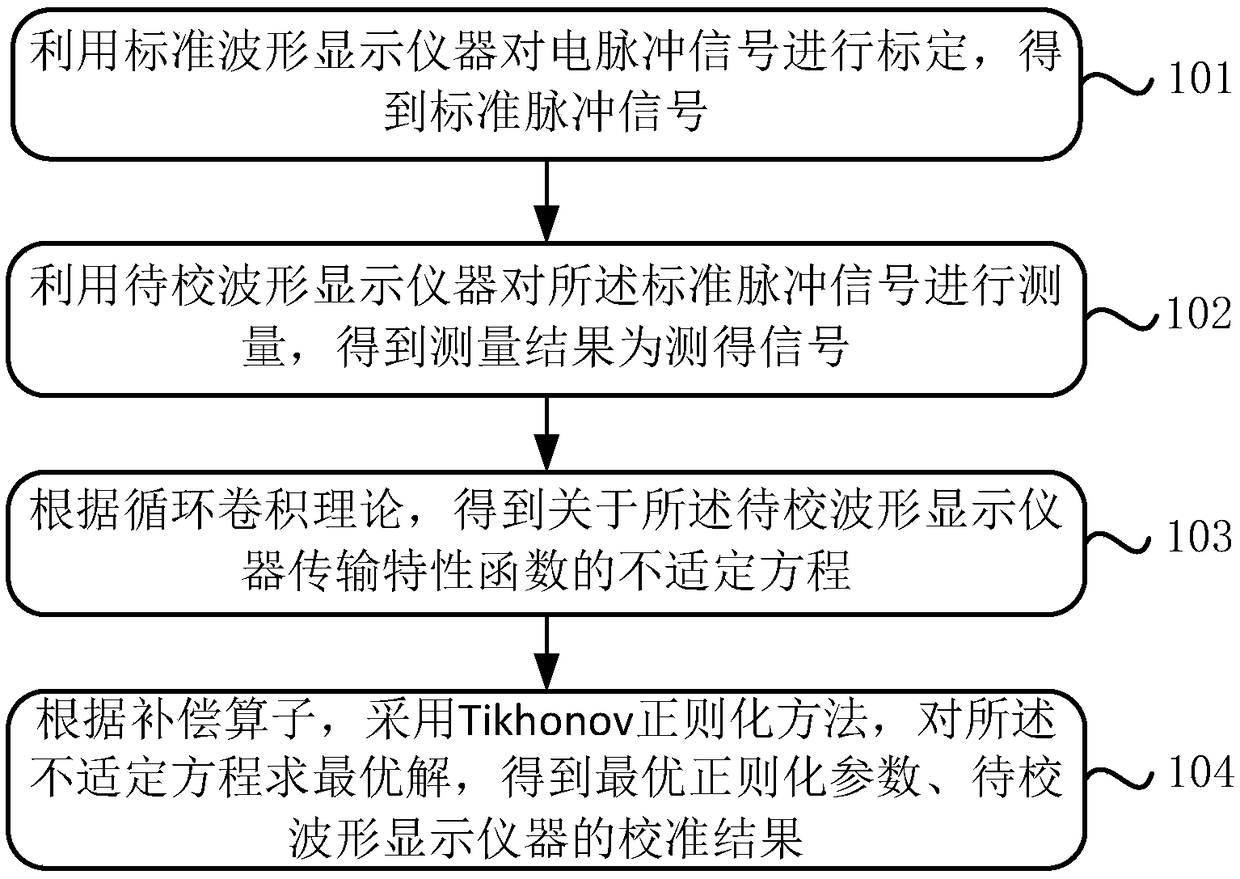
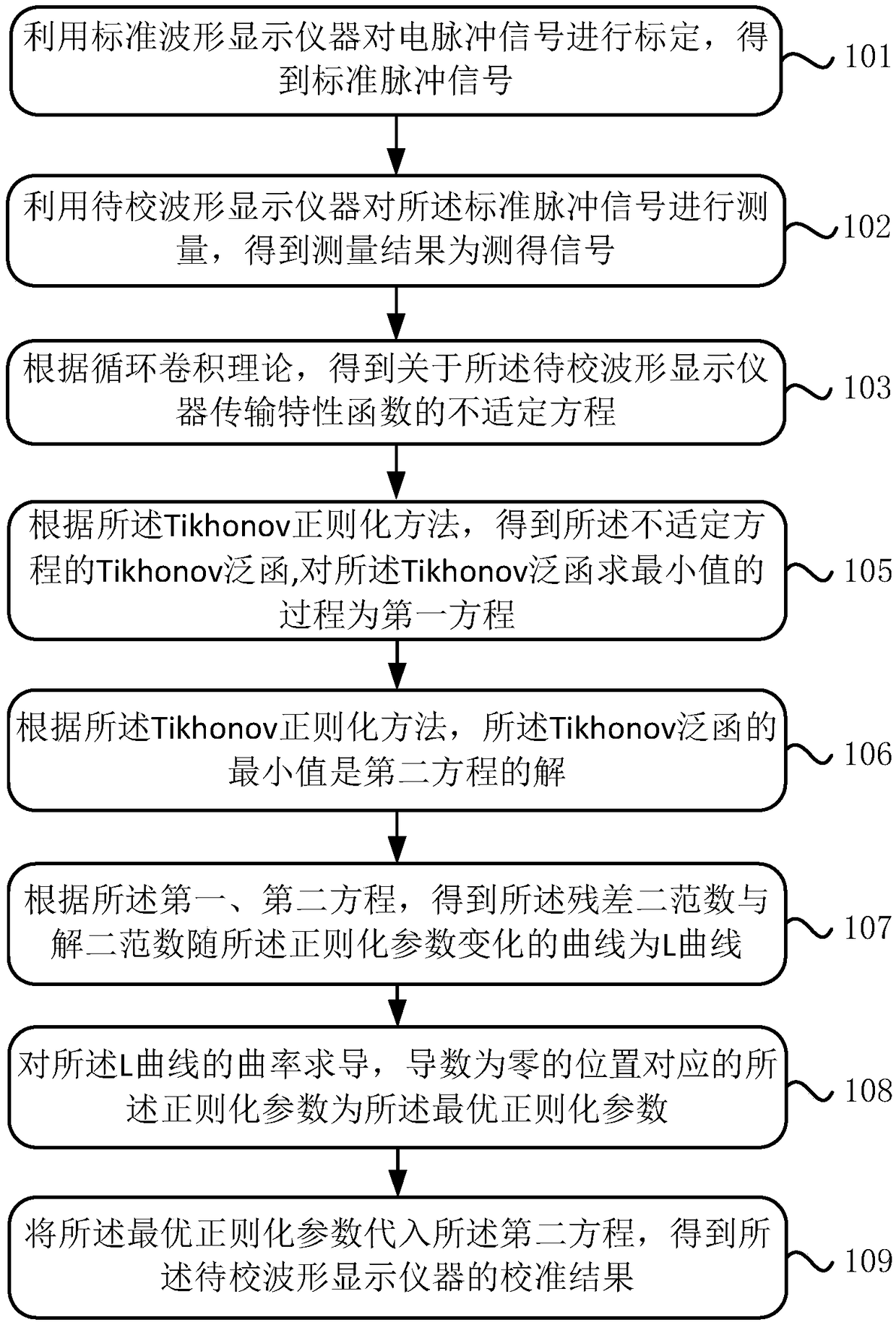
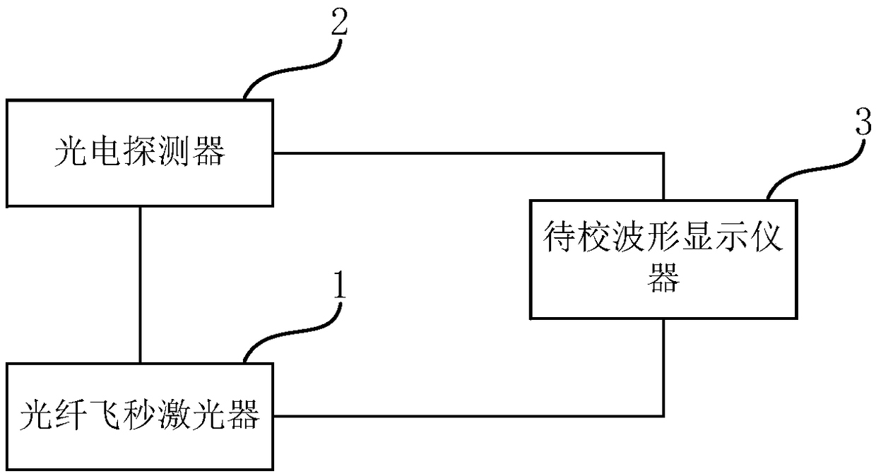
The invention discloses a waveform calibration method and device, so as to solve the problems that the existing method and the device are inaccurate in waveform calibration and the calibration processhas ill-posedness. The method comprises steps: a standard waveform display instrument is used to calibrate electric pulse signals, and standard pulse signals are obtained; a to-be-calibrated waveformdisplay instrument is used to measure the standard pulse signals to obtain measurement signals; according to a cyclic convolution theory, an ill-posed equation for a transmission characteristic function of the to-be-calibrated waveform display instrument is obtained; and according to a compensation operator, a regularization method is adopted to seek the optimal solution of the ill-posed equation, and the optimal regularization parameters and a calibration result are obtained. The device comprises a fiber femtosecond laser, a photoelectric detector and the to-be-calibrated waveform display instrument, wherein the photoelectric detector receives optical pulse signals generated by the fiber femtosecond laser, and electric pulse signals are generated; and the to-be-calibrated waveform display instrument receives the electric pulse signals for measurement. Thus, deconvolution of signals in a time domain can be objectively and accurately realized.

Description

technical field [0001] The invention relates to the field of pulse measurement, in particular to a waveform calibration method and device. Background technique [0002] Due to the existence of signal noise, the waveform calibration process in the field of pulse metering cannot directly obtain a stable solution through frequency domain division and deconvolution, which is ill-posed. This ill-posedness is mainly reflected in two aspects. On the one hand, due to the limitation of objective conditions, that is, part of the known information of a given solution is often underdetermined or overdetermined, which will lead to the solution being not unique or the solution does not exist. On the other hand, the solution of the inverse problem often does not have a continuous dependence on the input data. The traditional waveform calibration solution method first uses a filter to filter out the signal noise, and then performs frequency domain deconvolution. However, due to the unknown...

Claims


Application Information

Patent Timeline
IPC IPC(8): G01R35/00
CPCG01R35/005
Inventor 刘爽龚鹏伟姜河谌贝谢文
Owner BEIJING INST OF RADIO METROLOGY & MEASUREMENT
Learn More