Moving degaussing DEVICE

A degaussing device and degaussing coil technology, which is applied in the field of degaussing magnetic labels, can solve the problems of uneven distribution of degaussing magnetic field, low degaussing efficiency, and inability to move the degaussing magnetic field, so as to improve and book borrowing efficiency, flexible and convenient use, and reduce labor costs Effect

Pending Publication Date: 2018-12-11
浙江行雨网络科技有限公司
View PDF3 Cites 4 Cited by
  • Summary
  • Abstract
  • Description
  • Claims
  • Application Information

AI Technical Summary

Problems solved by technology

[0002] As a means of anti-theft, magnetic tags are widely used in commodity sales, book borrowing and other fields. In these fields, the degaussing of magnetic tags is generally done manually. This method can only remove one or several magnetic tags at a time, and the degaussing The effect is not ideal, especially when the magnetic label pasted on iron or other metal objects is degaussed, it often takes multiple degaussing operations to eliminate the magnetic mark of the magnetic label, and the degaussing efficiency is low; at the same time, the degaussing device currently used is generally a single The degaussing device of the degaussing coil has a fixed degaussing magnetic field and a fixed degaussing range. The distribution of the degaussing magnetic field is uneven, and the degaussing magnetic field cannot be moved, which affects the degaussing success rate and degaussing efficiency of the magnetic label, especially when multiple magnetic labels are eliminated at the same time. Completely unable to meet the degaussing requirements

Method used


Image

  • Moving degaussing DEVICE
  • Moving degaussing DEVICE
  • Moving degaussing DEVICE

Examples


Embodiment Construction

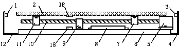
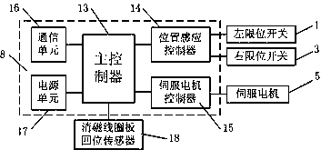
[0014] Such as Figure 1 ~ Figure 2 As shown, a mobile degaussing device in the present invention includes a degaussing coil plate 2, a servo motor 5, a screw rod 10, a left limit switch 1, a right limit switch 3, a degaussing coil plate return sensor 18, and a bottom bracket plate 6 , left screw mandrel cover 11, right screw mandrel cover 7, power supply and control unit 8, screw mandrel support sleeve 9, left limit switch strut 12, right limit switch strut 4.

[0015] Wherein, the servo motor 5 is fixed on the bottom support plate 6, the screw mandrel 10 is supported on the bottom support plate 6 by the screw mandrel support sleeve 9, and the degaussing coil plate 2 is supported on the screw mandrel by the left screw mandrel cover 11 and the right screw mandrel cover 7. 10 on.

[0016] The left limit switch 1 and the right limit switch 3 are respectively installed at the left and right ends of the degaussing coil plate 2, and the left limit switch 1 and the right limit swit...


PUM


Abstract

The invention discloses a moving degaussing device, which comprises a degaussing coil plate, a screw rod, a servo motor, a power supply and control unit, left and right limit switches and a support thereof, left and right screw rod sleeves, a screw rod support sleeve, a bottom support plate and the like. The degaussing coil plate is supported on the screw rod through the left and right screw rod sleeves, the screw rod is fixed on the bottom bracket plate through the screw rod support sleeve, and the servo drive motor is fixed on the bottom bracket plate; A servo drive motor drives the screw rod to drive the degaussing coil plate to move left and right, and a limit switch is arranged at both ends of the degaussing coil plate to control the moving distance of the degaussing coil plate. The power supply and control unit provides power for the moving degaussing device and controls the servo motor as well as realizes the communication with other equipment. The moving degaussing device provided by the invention realizes simultaneous degaussing of a plurality of magnetic labels, greatly improves the simultaneous degaussing success rate of the plurality of magnetic labels, has a good degaussing effect, and can be widely applied to occasions where a large number of magnetic labels need to be simultaneously degaussed, such as commodity sales and book borrowing.

Description

technical field [0001] The invention relates to the field of magnetic label degaussing, in particular to a simultaneous degaussing technology for multiple magnetic labels. technical background [0002] As a means of anti-theft, magnetic tags are widely used in commodity sales, book borrowing and other fields. In these fields, the degaussing of magnetic tags is generally done manually. This method can only remove one or several magnetic tags at a time, and the degaussing The effect is not ideal, especially when the magnetic label pasted on iron or other metal objects is degaussed, it often takes multiple degaussing operations to eliminate the magnetic mark of the magnetic label, and the degaussing efficiency is low; at the same time, the degaussing device currently used is generally a single The degaussing device of the degaussing coil has a fixed degaussing magnetic field and a fixed degaussing range. The distribution of the degaussing magnetic field is uneven, and the degau...

Claims


Application Information

Patent Timeline
IPC IPC(8): H01F13/00
CPCH01F13/006
Inventor 马子余沈博侃梁文锋阮棋波董方武
Owner 浙江行雨网络科技有限公司
Why Eureka
Try Eureka