
An electric power protection measuring and controlling device convenient in heat dissipation

A measurement and control device and power protection technology, which is applied in the direction of emergency protection circuit devices, circuit devices, substation/power distribution device shells, etc., can solve problems such as unable to discharge heat from power equipment, affecting normal operation of power equipment, and affecting work stability. , to achieve the effect of simple structure, improved aesthetics and reduced cleaning intensity

Inactive Publication Date: 2018-12-11
ANHUI JINAIER ELECTRICAL APPLIANCE TECH
View PDF18 Cites 5 Cited by
  • Summary
  • Abstract
  • Description
  • Claims
  • Application Information

AI Technical Summary

Problems solved by technology

[0002] The protection measurement and control device is a comprehensive protection device integrating protection, measurement, control, monitoring, communication, event recording, fault recording, operation error prevention and other functions. It is a comprehensive automation system for power stations such as substations and power plants. Most of the existing power protection measurement and control devices are simple in structure and poor in heat dissipation, and cannot discharge the heat generated by power equipment in time. If it goes on for a long time, it will not only affect the normal operation of power equipment, but also reduce its performance. The service life will even lead to the occurrence of safety accidents, and the practicability is poor. In addition, the cooling devices of most power protection measurement and control devices will generate a lot of vibration when they are working, which not only affects the stability of their work, but also easily generates noise pollution.

Method used


Image

  • An electric power protection measuring and controlling device convenient in heat dissipation
  • An electric power protection measuring and controlling device convenient in heat dissipation
  • An electric power protection measuring and controlling device convenient in heat dissipation

Examples


Embodiment Construction

[0021] The following will clearly and completely describe the technical solutions in the embodiments of the present invention with reference to the accompanying drawings in the embodiments of the present invention. Obviously, the described embodiments are only some, not all, embodiments of the present invention. Based on the embodiments of the present invention, all other embodiments obtained by persons of ordinary skill in the art without making creative efforts belong to the protection scope of the present invention.

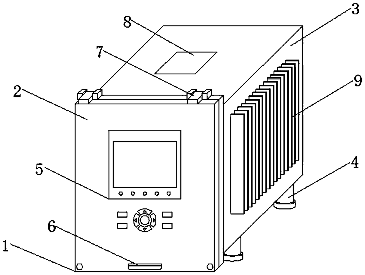
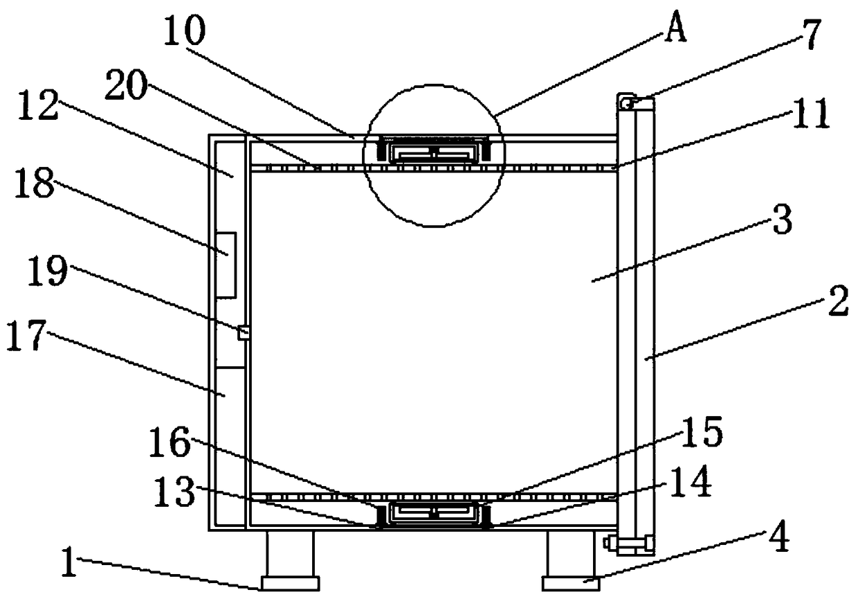
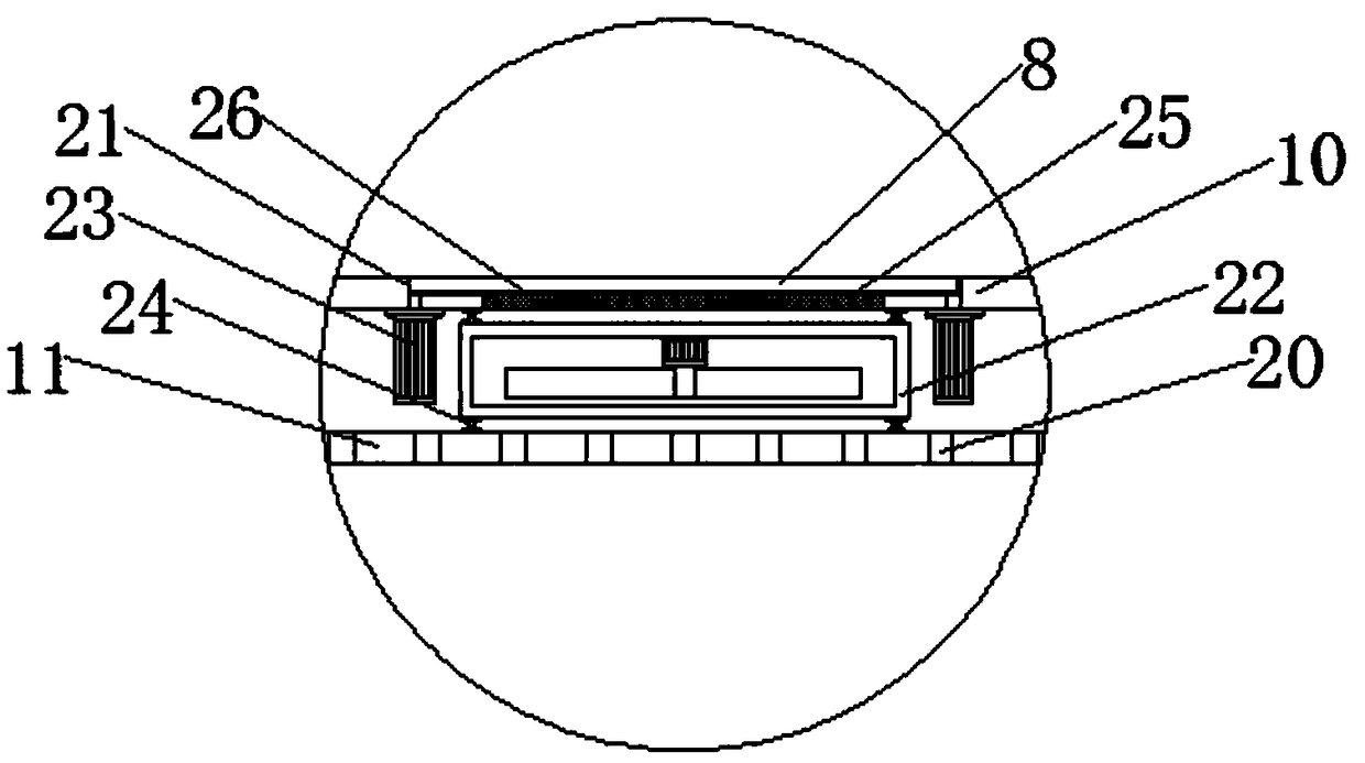
[0022] see Figure 1-5, the present invention provides a technical solution: a power protection measurement and control device that facilitates heat dissipation, including a device body 1, a panel 2, a housing 3, a foot 4, a display screen 5, a handle 6, a rotating shaft 7, an upper baffle 8, a heat dissipation Sheet 9, outer shell 10, inner shell 11, control box 12, lower slot 13, lower baffle 14, exhaust fan 15, first electric push rod 16, battery 17, ARM mi...


PUM


Abstract

The invention discloses an electric power protection measuring and controlling device convenient in heat dissipation, the front surface of the device body is provided with a panel, a housing is mounted on the back of the panel, the outer side of the housing is provided with a housing, An upper slot is installed in that middle of the top end of the housing, An upper baffle is mount inside that upper slot, A second electric push rod is mounted on both sides of the bottom end of the upper baffle, A blower is mounted on the bottom of the upper slot, A low slot is provided in that middle of the bottom end of the house, A lower baffle is mounted inside the lower slot, A first electric push rod is mounted on both sides of the top end of the lower baffle, A suction fan is mounted on that top of the lower slot, an inner shell is mounted on the inner side of the outer shell, The rear side of the shell is provided with a control box, and the bottom of the shell is provided with a leg. The suctionfan and the blower of the invention are used together, and the two cooperate with each other to accelerate the air circulation inside the device body, thereby avoiding dead angles and completely extracting heat quickly and quickly, so that the heat dissipation efficiency of the device body is improved, and the working cost is reduced.

Description

technical field [0001] The invention relates to the technical field of a power protection measurement and control device, in particular to a power protection measurement and control device that facilitates heat dissipation. Background technique [0002] The protection measurement and control device is a comprehensive protection device integrating protection, measurement, control, monitoring, communication, event recording, fault recording, operation error prevention and other functions. It is a comprehensive automation system for power stations such as substations and power plants. Most of the existing power protection measurement and control devices are simple in structure and poor in heat dissipation, and cannot discharge the heat generated by power equipment in time. If it goes on for a long time, it will not only affect the normal operation of power equipment, but also reduce its performance. The service life will even lead to the occurrence of safety accidents, and the ...

Claims


Application Information

Patent Timeline
IPC IPC(8): H02B1/26H02B1/56H02B1/54H02H1/00
CPCH02B1/26H02B1/54H02B1/565H02H1/00
Inventor 艾蒙雁
Owner ANHUI JINAIER ELECTRICAL APPLIANCE TECH
Learn More