A kind of surgical forceps for mandibular angle fracture reduction

A technique of surgical forceps and mandibular, which is applied in the field of surgical forceps for the reduction of mandibular angle fractures. It can solve the problems of being unable to complete the reduction operation alone and expand the surgical field of view, and achieve the effect of reducing occlusion and facilitating surgical operations.

Active Publication Date: 2021-01-01
仝春实
View PDF1 Cites 0 Cited by
  • Summary
  • Abstract
  • Description
  • Claims
  • Application Information

AI Technical Summary

Problems solved by technology

[0005] The purpose of the present invention is to provide a surgical forceps for mandibular angle fracture reduction, to solve the technical problem in the prior art that the internal fixation forceps cannot pull the oral cavity tissue to expand the surgical field of view and cannot complete the reduction operation alone

Method used


Image

  • A kind of surgical forceps for mandibular angle fracture reduction
  • A kind of surgical forceps for mandibular angle fracture reduction
  • A kind of surgical forceps for mandibular angle fracture reduction

Examples


Embodiment 1

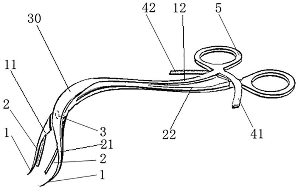
[0025] like figure 1 As shown, the surgical forceps for mandibular angle fracture reduction includes a first forceps body and a second forceps body, the first forceps body includes a first handle segment 12 and a first jaw segment 21, and the second forceps body includes a second handle segment 22 and a second forceps body The second jaw section 11, between the first jaw section 21 and the first handle section 12, and between the second jaw section 11 and the second handle section 22 are provided so that the two arc transitions are connected and form a 95-degree The angled bending section 30, the first jaw section 21 has a hollow section, the second jaw section 11 is penetrated in the hollow section and is hinged with the first jaw section 21 through the pin shaft 3, the two jaw sections The front ends of the two pincer beaks 1 are formed, and the two pincer beaks 1 gradually bend inward and extend forward along the corresponding pincer body. The two pincer beaks 1 cooperate w...

Embodiment 2

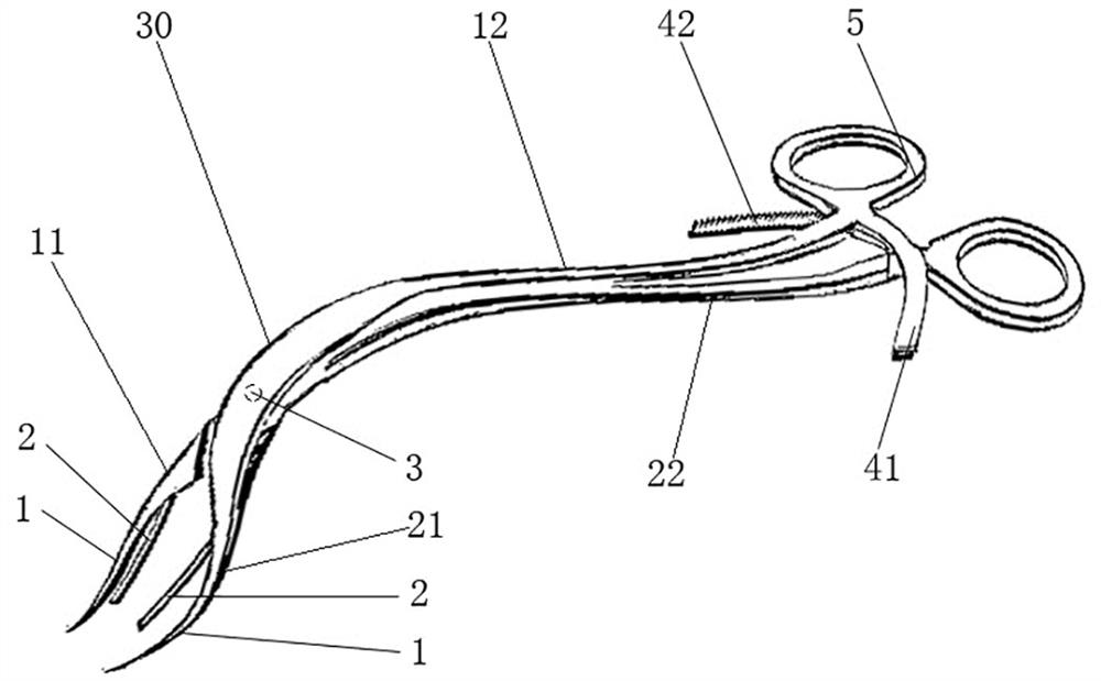
[0035] The difference between it and Embodiment 1 is mainly that: between the first jaw segment 21 and the first handle segment 12 and between the second jaw segment 11 and the second handle segment 22, there are arc-shaped transition connections between the two. A bent section 30 with an included angle of 120 degrees is formed.

[0036] In fact, the included angle between each jaw segment and the corresponding handle segment can range from 90 to 120 degrees, so that the surgical field of view after pulling can be guaranteed to the greatest extent, and the doctor's operation can be ensured. The 90-degree included angle can effectively hook and pull the oral tissue, which is convenient for the doctor to apply force; while the 120-degree included angle makes the surgical forceps tend to pull and pick when pulling the oral tissue (such as figure 2 ), this pulling action is beneficial to open the deeper oral tissues, which is convenient for the doctor to observe the deep mandibul...

Embodiment 3

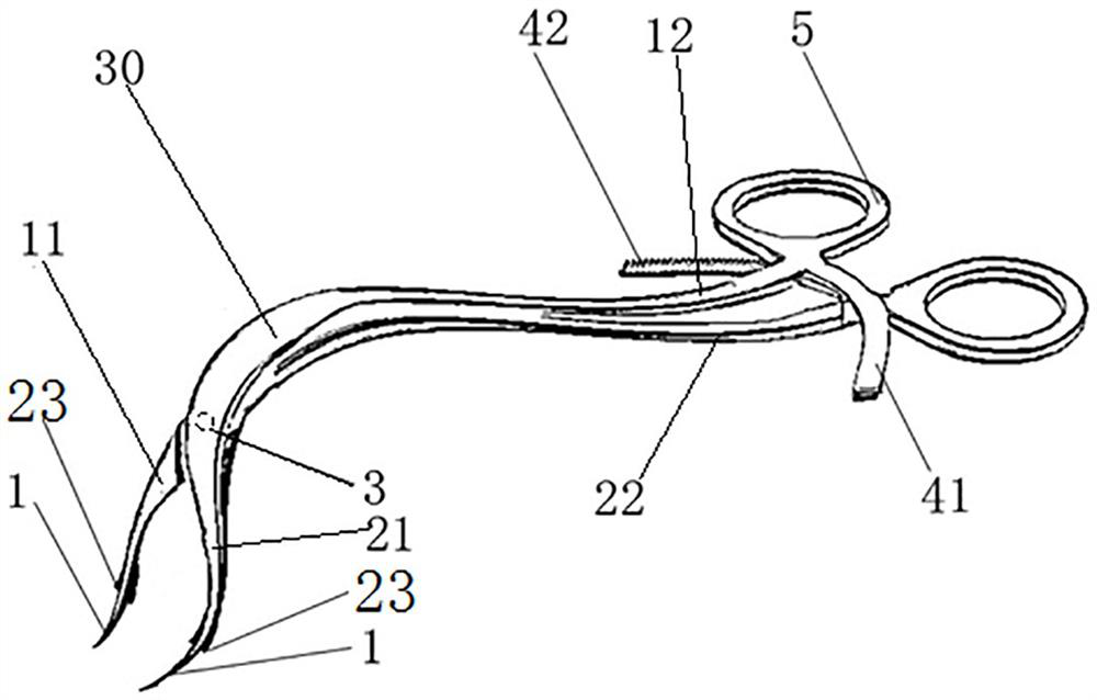
[0038] It differs from Embodiment 1 mainly in that: the layout of the supporting top surface is different. The top pillar structure that adopts in embodiment 1, in the present embodiment, such as image 3 As shown, an integrally formed large-diameter section 23 is provided behind the pliers beak 1 to form a supporting structure, and the front end surface of the large-diameter section 23 forms a stepped structure with the corresponding pliers beak 1, and the front end surface of the large-diameter section forms a supporting surface. . The structure of the supporting structure in this embodiment is simpler, which reduces the difficulty of production, further reduces the production cost, and is beneficial to popularization.


PUM


Abstract

The invention relates to operating forceps used for mandibular angle fracture reduction. The operating forceps comprise a first forcep body and a second forcep body. The two forcep bodies are hinged through a pin roll. Each forcep body comprises a forcep claw section on the front part and a handle section on the rear part. The front end of the forcep claw section is provided with a forcep mouth which is used to insert into a corresponding auxiliary retention hole by the side of a fracture line to apply a fold reset force. The forcep claw section on each forcep body is connected with a corresponding handle section in a bending transition manner through a bending section. The pin roll is arranged on the two forcep claw sections, so that the operating forceps used for mandibular angle fracture reduction form an oral cavity drag hook structure. The two forcep claw sections form a hook head of the oral cavity drag hook structure. The two handle sections form a handle of the oral cavity draghook structure. The pin roll is arranged on the two forcep claw sections, so that opening and closing degree of the two forcep claw sections is relatively low. When an oral cavity drag hook formed bythe operating forceps pulls an oral tissue, the oral tissue overflown between the two forcep claw sections is few, so as to reduce visual field shielding, and a single person can perform a reductionoperation.

Description

technical field [0001] The invention relates to a surgical forceps for mandibular angle fracture reduction. Background technique [0002] When the mandibular angle is fractured, the extraoral approach or the intraoral approach is used for reduction surgery according to the fracture situation. Extraoral approach reduction surgery requires an incision on the face at the fracture site, drilling auxiliary retention holes on both sides of the fracture line, inserting the beaks of the fracture surgical forceps into the two auxiliary retention holes, and clamping the surgical forceps to make the fracture The mandibular angle bones on both sides of the line move inward and remain fixed. At this time, a fixation device such as a fixation frame can be implanted for post-operative fixation. The difference between the intraoral approach and the extraoral approach is that the above operations are completed inside the oral cavity. Therefore, surgery through the intraoral approach can avo...

Claims


Application Information

Patent Timeline
Patent Type & Authority Patents(China)
IPC IPC(8): A61B17/56A61B17/28
CPCA61B17/2812A61B17/282A61B17/2833A61B17/56A61B2017/564
Inventor 仝春实彭利伟王永功王希乾骆书文
Owner 仝春实
Why Eureka
Try Eureka