
A shell embossing device for electronic product production

A technology for electronic products and shells, which is applied in the field of shell embossing devices for electronic product production, which can solve the problems of shell clamping work, single type of embossing, offset of embossing work, etc., so as to improve work efficiency and embossing quality , The effect of simple operation of the device

Active Publication Date: 2019-12-13
RUIAN GREAT PRINTING & PACKAGING MACHINERY
View PDF6 Cites 0 Cited by
  • Summary
  • Abstract
  • Description
  • Claims
  • Application Information

AI Technical Summary

Problems solved by technology

[0004] The purpose of the present invention is to provide a shell embossing device for electronic product production, to solve the problem that most of the electronic product shell embossing equipment currently on the market has a single embossing type, and cannot simultaneously produce a variety of embossed shells. The quality of the embossing is not high, and the production efficiency is low. When embossing, most of the shells of electronic products are manually controlled. There is no suitable fixture, and the embossing work is prone to deviation. At the same time, some simple fixtures cannot be used for electronic equipment shells of different sizes. Problems with clamping work

Method used


Image

  • A shell embossing device for electronic product production
  • A shell embossing device for electronic product production
  • A shell embossing device for electronic product production

Examples


Embodiment Construction

[0026] The technical solutions of the present invention will be clearly and completely described below in conjunction with the embodiments. Apparently, the described embodiments are only some of the embodiments of the present invention, not all of them. Based on the embodiments of the present invention, all other embodiments obtained by persons of ordinary skill in the art without creative efforts fall within the protection scope of the present invention.

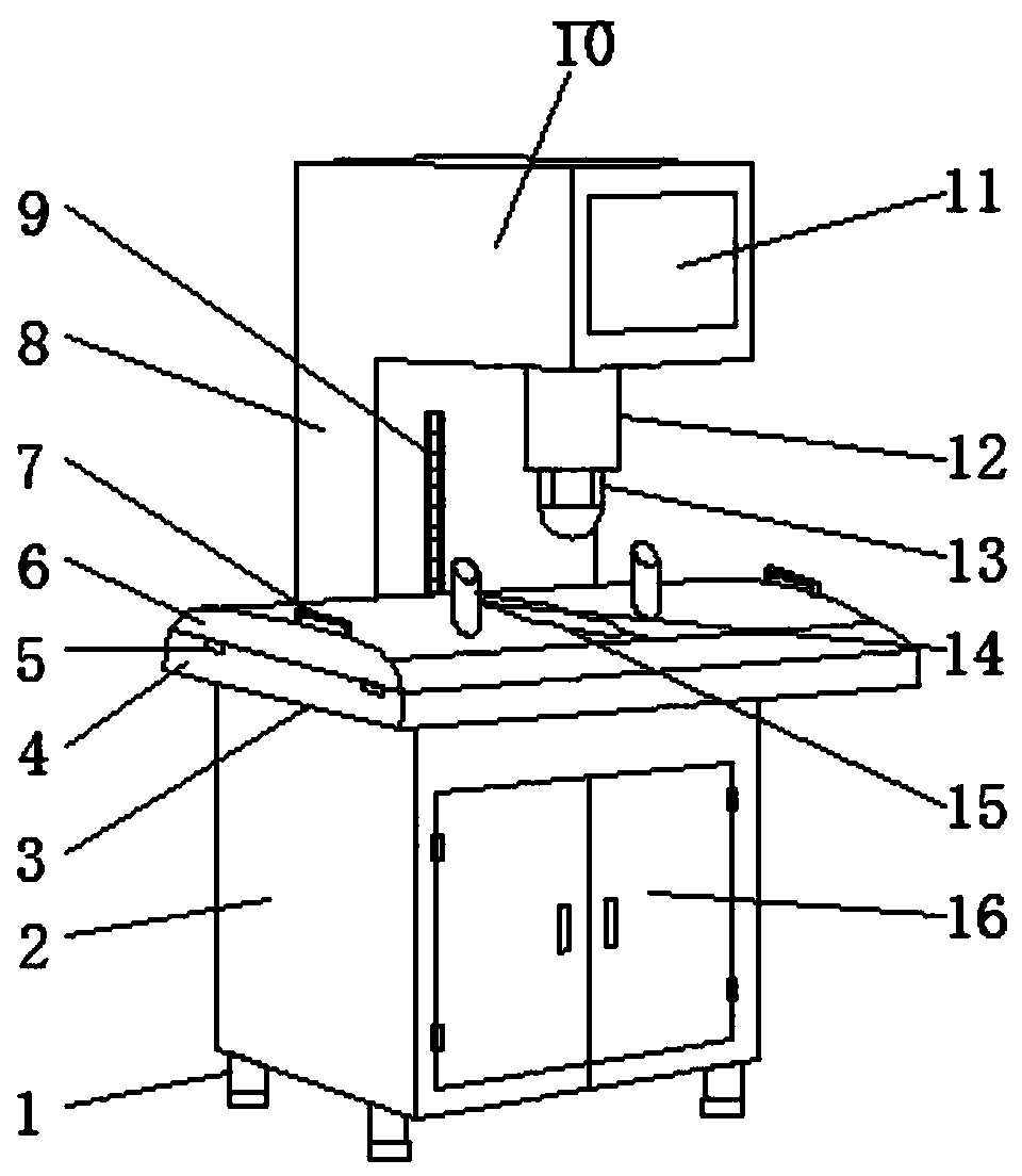
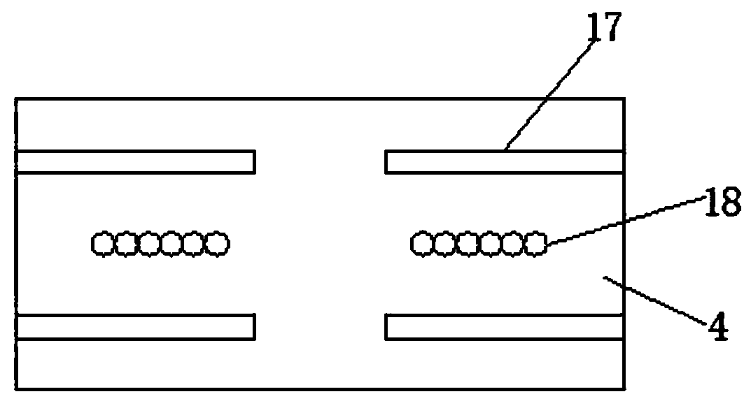
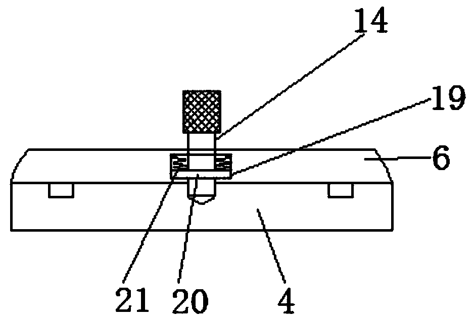
[0027] like Figure 1-5 As shown, a shell embossing device for the production of electronic products includes an outer box 2, a clamping device 3 and a drive box 10, the front side of the outer box 2 is provided with a locker 16, and the bottom four corners of the outer box 2 are Pads 1 are provided at the positions respectively, a clamping device 3 is provided on the top of the outer box 2, and a support plate 8 is provided on one side of the clamping device 3, and the bottom end of the support plate 8 is fixed on the top ...


PUM


Abstract

The invention discloses a shell embossing device for electronic product production. The shell embossing device for electronic product production comprises an outer box, a clamping device and a drivingbox. A storage cabinet is arranged on the front end side face of the outer box, and cushion blocks are separately arranged at the four corners of the bottom of the outer box. The clamping device is arranged at the top of the outer box. A supporting plate is arranged on one side of the clamping device. The bottom end of the supporting plate is fixedly arranged on the top surface of the outer box.The driving box is fixedly arranged on one side of the top end of the supporting plate. An inserting hole is pulled up upwards, a spring is compressed, and an inserting rod is moved out of the inserting hole. Handles on both sides of clamping plates are pushed, so that the clamping plate is moved left and right in the direction of a sliding groove, electronic equipment shells are clamped and fixedbetween grooves of the two clamping plates, the inserting rod is loosened, the spring applies elastic force to a baffle, the baffle drives the inserting rod to move downwards, and the inserting rod is inserted into the inserting hole, so that the clamping plate is prevented from shifting during embossing. The electronic product shells with different sizes are conveniently clamped and fixed, and embossing of the electronic product shells with different sizes is achieved.

Description

technical field [0001] The invention relates to the field of electronic product equipment, in particular to a shell embossing device for electronic product production. Background technique [0002] With the development of my country's economy and society, electronic products have gradually become an indispensable part of people's lives. Electronic products developed the fastest and were most widely used in the 20th century, and became an important symbol of the development of modern science and technology. In order to adapt to With the rapid development of electronic products, the production machinery of electronic products is also keeping pace with the rapid development. Embossing equipment for electronic product shells is an important production device for the production of electronic products and has been widely used. [0003] However, most of the electronic product case embossing equipment currently on the market has a single type of embossing, and cannot produce a variet...

Claims


Application Information

Patent Timeline
Patent Type & Authority Patents(China)
IPC IPC(8): B23P9/02B23Q3/06B23Q13/00B25H3/02
CPCB23P9/02B23Q3/062B23Q13/00B25H3/02
Inventor 狄祥
Owner RUIAN GREAT PRINTING & PACKAGING MACHINERY
Learn More