
Stable storage device with classifying function for electronic elements

A technology of electronic components and storage devices, which is applied in the direction of unloading devices, packaging, external accessories, etc., can solve the problems of difficult access and use of electronic components, insufficient flexibility, messy storage of electronic components, etc., to achieve firm support, good cushioning elasticity, Easy to move and adjust the effect of the device body

Inactive Publication Date: 2018-12-14
杜都
View PDF5 Cites 3 Cited by
  • Summary
  • Abstract
  • Description
  • Claims
  • Application Information

AI Technical Summary

Problems solved by technology

[0004] The purpose of the present invention is to provide a sortable and stable storage device for electronic components, to solve the problem that the existing electronic components proposed in the background technology need to be stored when they are idle, and the volume and shape of different electronic components The structure and the length of the pins are different, which leads to the problem of messy storage of electronic components. At the same time, there is a problem of wasting space when the components are interlaced, and the structure of the storage device itself There is also the problem of not being flexible enough, and it is difficult to flexibly take and use various electronic components

Method used


Image

  • Stable storage device with classifying function for electronic elements
  • Stable storage device with classifying function for electronic elements
  • Stable storage device with classifying function for electronic elements

Examples


Embodiment Construction

[0026] The following will clearly and completely describe the technical solutions in the embodiments of the present invention with reference to the accompanying drawings in the embodiments of the present invention. Obviously, the described embodiments are only some, not all, embodiments of the present invention. Based on the embodiments of the present invention, all other embodiments obtained by persons of ordinary skill in the art without making creative efforts belong to the protection scope of the present invention.

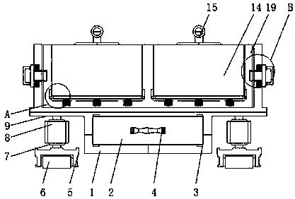
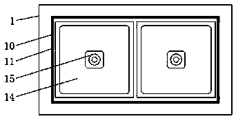
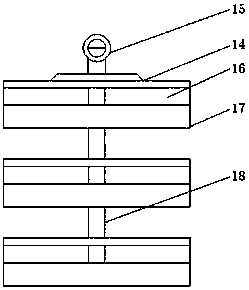
[0027] see Figure 1-5, the present invention provides a technical solution: a classifiable and stable storage device for electronic components, including a base 1, a drawer 2, a connecting block 3, a handle 4, a fixing seat 5, a roller 6, a connecting shaft 7, and a rotating column 8 , middle seat 9, inner groove 10, receiving plate 11, connecting slat 12, buffer spring 13, built-in object seat 14, connecting fixed rod 15, hollow opening 16, bottom plate 17, ...


PUM


Abstract

The invention relates to a stable storage device with a classifying function for electronic elements. The stable storage device with the classifying function for the electronic elements comprises a base and fixing seats, an extraction box is connected to the middle of the base, and connecting blocks are fixed to the periphery of the extraction box. A handle is arranged at the front end of the extraction box, and the extraction box is fixedly connected with the handle. Idler wheels are installed at the lower ends of the middles of the fixing seats, and the fixing seats are located on the left and right sides of the bottom end of the base. Connecting shafts are connected to the top ends of the fixing seats, and rotating columns are installed at the upper ends of the connecting shafts. A middle layer seat is installed at the upper end of the base, and an inner seat is connected to the interior of the middle layer seat. An inner groove is formed in the inner end of the inner seat, and a supporting plate is installed at the bottom end of the inner groove. The stable storage device with the classifying function for the electronic elements has the beneficial effects that the base and theextraction box are arranged, and through sliding of the base and the extraction box, the extraction box can be driven to slide in the base, so that the extraction box is conveniently extracted out tostore the electronic elements with medium sizes through inner chamber inside the extraction box.

Description

technical field [0001] The invention relates to the technical field of electronic components, in particular to a sortable and stable storage device for electronic components. Background technique [0002] Electronic components are basic elements in electronic circuits, usually individually packaged, and have two or more leads or metal contacts. Electronic components must be connected to each other to form an electronic circuit with specific functions, such as: amplifier , radio receivers, oscillators, etc., one of the common ways to connect electronic components is to solder to a printed circuit board, and most electronic components need to be stored conveniently. [0003] Existing electronic components need to be stored when they are idle, and different electronic components have different volumes, shapes, structures, and lengths of pins, which leads to the problem of messy storage of electronic components, and at the same time When the various components are interlaced wi...

Claims


Application Information

Patent Timeline
IPC IPC(8): B65D25/24B65D25/38B65D6/06B65D81/07B65D81/05B65D85/86
CPCB65D25/24B65D7/10B65D9/08B65D11/12B65D25/38B65D81/05B65D81/07B65D2585/86
Inventor 杜都
Owner 杜都
Learn More