
Cloth feeding mechanism for automatically improving coiling

A cloth feeding mechanism and cloth feeding technology, applied in the field of sewing machines, can solve the problems of unadjustable thread take-up effect, inability to better adapt to different cloth, poor adaptability, etc.

Active Publication Date: 2018-12-14
JACK SEWING MASCH CO LTD
View PDF7 Cites 21 Cited by
  • Summary
  • Abstract
  • Description
  • Claims
  • Application Information

AI Technical Summary

Problems solved by technology

[0007] However, in the cloth feeding mechanism driven by a single motor and the cloth feeding mechanism driven by a double motor, the tooth lifting mechanism is driven by the main motor and the main shaft, and the end of the main shaft far away from the main motor is also equipped with a thread take-up and pricking cloth mechanism. The action of the tooth lifting mechanism and the action of the thread picking and piercing mechanism are synchronous, or in other words, the tooth lifting mechanism and the thread picking and piercing mechanism are in synchronous phase with respect to the main shaft, so that the feeding teeth in the cloth feeding mechanism are in the up and down direction. The reciprocating motion on the thread take-up bar is synchronized with the action of the thread take-up lever in the thread take-up and stabbing mechanism, that is, the above time points t1 and t2 are fixed and cannot be adjusted, which leads to the same thread take-up effect of the sewing machine and cannot be adjusted
However, different thicknesses of sewing materials have different requirements on the thread take-up effect, which makes the cloth feeding mechanism of the sewing machine in the prior art less adaptable and cannot be better adapted to different cloth materials.

Method used

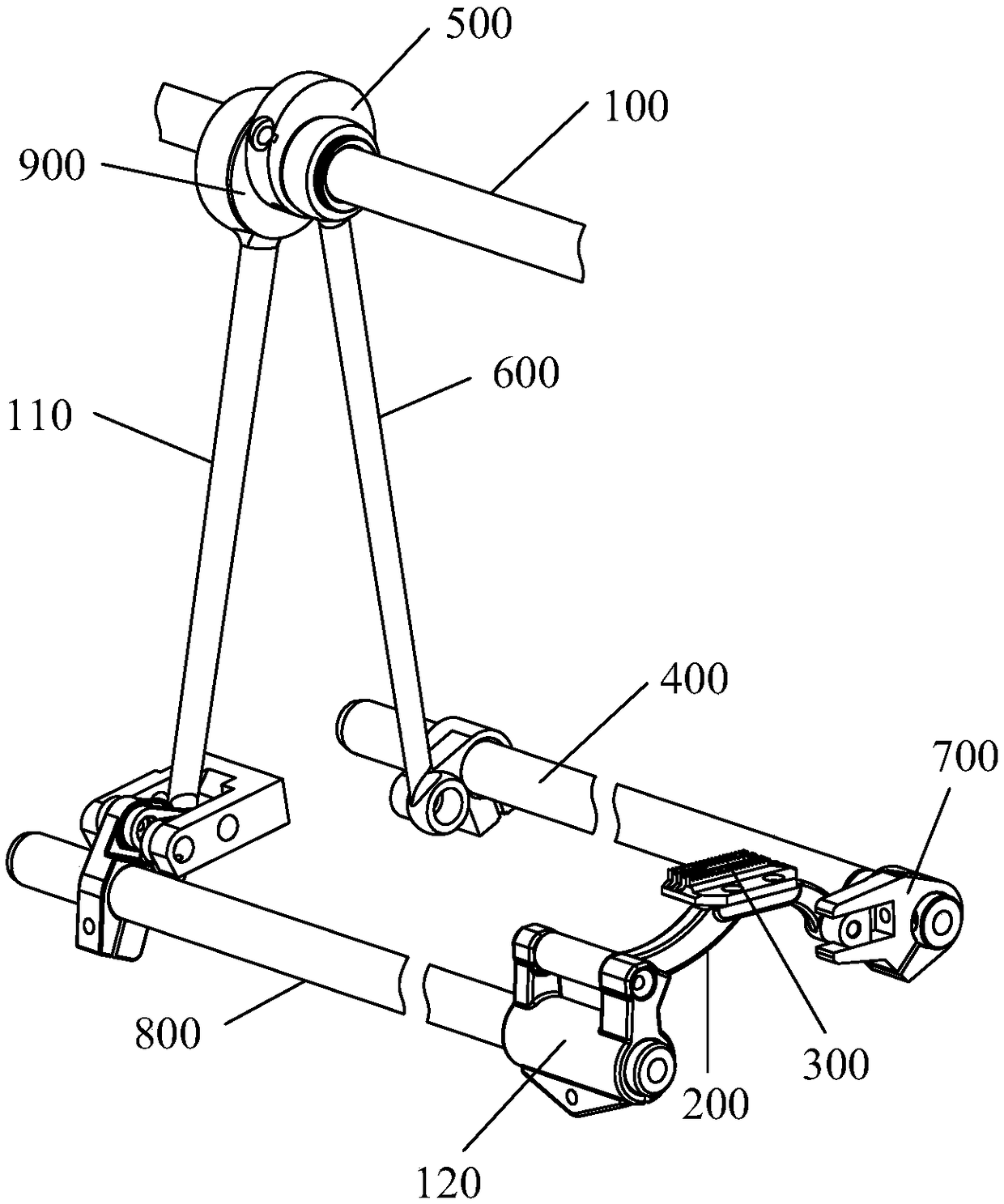
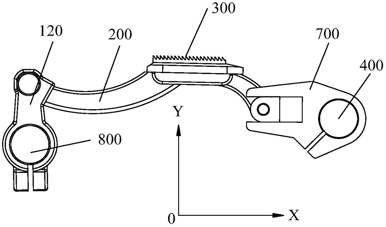
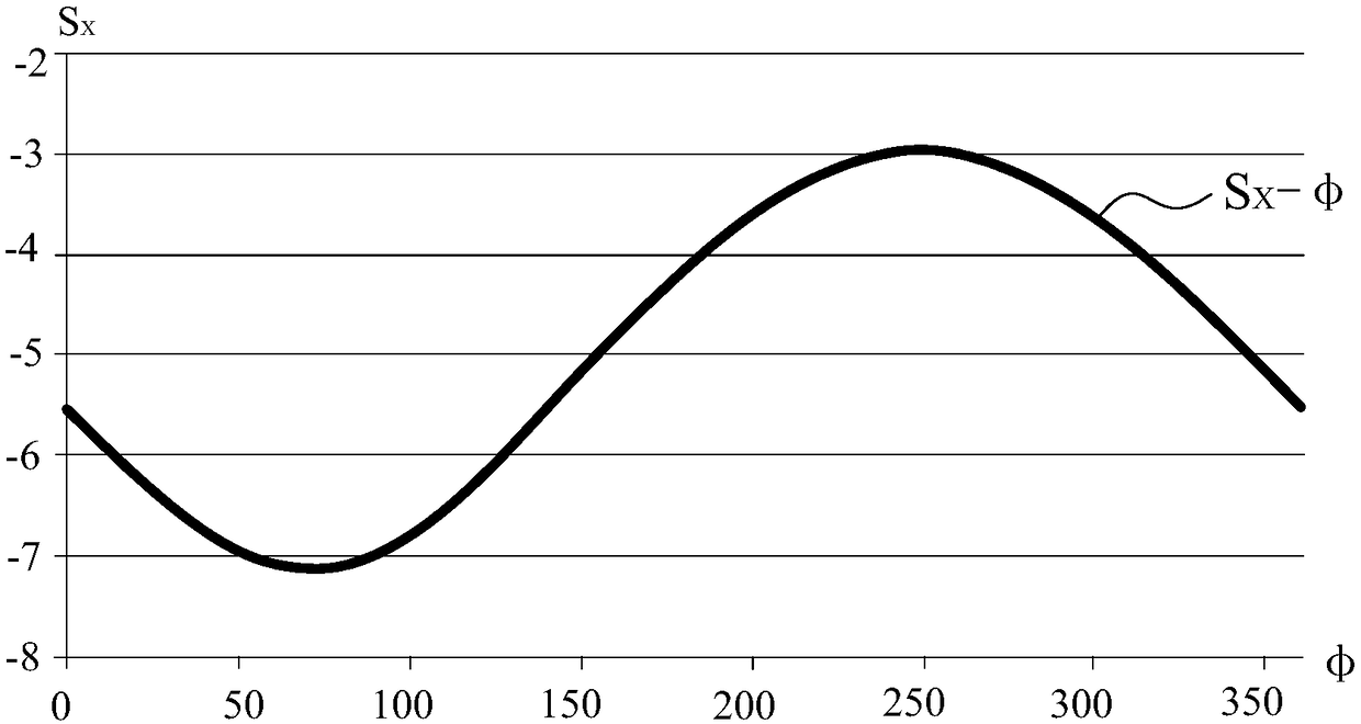

Image

  • Cloth feeding mechanism for automatically improving coiling
  • Cloth feeding mechanism for automatically improving coiling
  • Cloth feeding mechanism for automatically improving coiling

Examples


Embodiment Construction

[0065] The implementation of the present invention will be illustrated by specific specific examples below, and those skilled in the art can easily understand other advantages and effects of the present invention from the contents disclosed in this specification.

[0066] It should be noted that the structures, proportions, sizes, etc. drawn in the drawings of this specification are only used to match the content disclosed in the specification, for those who are familiar with this technology to understand and read, and are not used to limit the conditions for the implementation of the present invention. Therefore, there is no technical substantive meaning, and any modification of structure, change of proportional relationship or adjustment of size shall still fall within the scope of the disclosure of the present invention without affecting the functions and objectives of the present invention. within the scope of technical content. At the same time, terms such as "upper", "lo...


PUM


Abstract

The invention provides a cloth feeding mechanism for automatically improving coiling. The mechanism comprises a tooth frame, a feed dog fixed at an upper end of the tooth frame, a lifting assembly which is connected with one end of the tooth frame and is used for driving the tooth frame to reciprocate down and up, and a feeding assembly which is connected with the other end of the tooth frame andis used for driving the tooth frame to reciprocate back and forth and further includes a lifting driving motor which is independent of a main motor of a sewing machine, wherein the lifting driving motor is connected with the lifting assembly to drive the lifting assembly to move. The cloth feeding mechanism is advantaged in that the phase of the lifting assembly can be adjusted, a main shaft driven by the main motor in the sewing machine and a threading and needling mechanism connected with an end portion of the main shaft can be in the non-synchronous relationship, so the time point t1 at which the feed dog emerges upward from a needle plate and the time point t2 at which the feed dog sinks down into the needle plate can be changed, that is, cloth can be delivered in advance or delayed, suture tightening degrees are different, so the sewing machine has different tightening effects, and the sewing machine can be well adapted to sewing materials having different thicknesses.

Description

technical field [0001] The invention relates to a cloth feeding mechanism for automatically improving thread take-up. [0002] The present invention also relates to a sewing machine comprising the above-mentioned cloth feeding mechanism for automatically improving thread take-up. Background technique [0003] At present, the cloth feeding mechanism configured in the sewing machine mainly includes a tooth lifting assembly and a cloth feeding assembly. The tooth lifting assembly is connected with one end of the tooth frame to drive the tooth frame to reciprocate up and down. The tooth frame reciprocates back and forth, so the trajectory of the tooth frame is elliptical, such as Figure 5 shown. The cloth feeding mechanism in the sewing machine mainly has the following two structures: 1. Single motor drive: use one motor to drive the tooth lifting assembly and the cloth feeding assembly at the same time; 2. Double motor drive: use two motors to drive the tooth lifting assembly...

Claims


Application Information

Patent Timeline
IPC IPC(8): D05B27/02D05B27/24
CPCD05B27/02D05B27/24
Inventor 郑吉祝书伟应振华
Owner JACK SEWING MASCH CO LTD
Learn More