Deep hole blasting explosive cartridge

A technology of deep-hole blasting and blasting barrels, which is applied in the direction of blasting barrels, weapon accessories, offensive equipment, etc. It can solve the problems of PVC pipes that cannot be reused, misplaced cannons in the wrong position, and squibs that cannot be quickly recovered, etc., to achieve fast and stable charge, improve The success rate and the effect of improving work efficiency

Inactive Publication Date: 2018-12-14
CHINA UNIV OF MINING & TECH
View PDF5 Cites 4 Cited by
  • Summary
  • Abstract
  • Description
  • Claims
  • Application Information

AI Technical Summary

Problems solved by technology

[0003] The pre-blasting position of deep hole blasting is often located in the depth of long-distance drilling, and the depth of the drilling hole is usually greater than 15m. In order to send the explosives to the blasting site, the existing deep hole blasting technology mostly uses PVC pipes as the filling chamber for the explosive rolls , the follow-up feeding method uses PVC empty pipes with a length of about 1m for docking and delivery to deliver the front-end barrel to the predetermined position. During the transportation process, the cannon barrel is often broken, and the arrival and delivery rods are embedded in each other, which leads to the wrong position of the dumb gun and the delivery gun; because the PVC pipe is single-sectioned, it is impossible to quickly recover the dumb gun, and the PVC pipe that is sent in cannot be reused. use, resulting in a waste of resources; at the same time, when the explosives fail to explode, there is a great danger in the process of taking out the explosives from the drill hole

Method used


Image

  • Deep hole blasting explosive cartridge
  • Deep hole blasting explosive cartridge
  • Deep hole blasting explosive cartridge

Examples


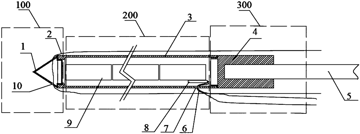
Embodiment 1

[0026] The present embodiment is based on the forward blasting charging method.

[0027] Such as figure 1 and Figure 5 As shown, a blasting cylinder for deep hole blasting includes a pilot device 100, a charging device 200 and a drug delivery device 300; Two through holes 10, a soft rope 2 passes through the through holes 10, half of the length of the soft rope 2 is greater than the depth of the drilled hole;

[0028] The charge device 200 includes a hollow cylindrical charge cartridge 3, a conical plug 1 is connected to one end of the charge cartridge 3, and a gun rope hole 7 is provided on the charge cartridge 3, and several explosive rolls 9 and A detonator 8 is used for detonation, and the gun rope 6 of the detonator 8 passes through the gun rope hole 7 and extends to the outer end of the borehole; When charging, the explosive rolls 9 are evenly arranged in the charge barrel in turn, and finally the detonator 8 is installed;

[0029] The drug delivery device 300 inclu...

Embodiment 2

[0037] The present embodiment is based on the forward blasting charging method.

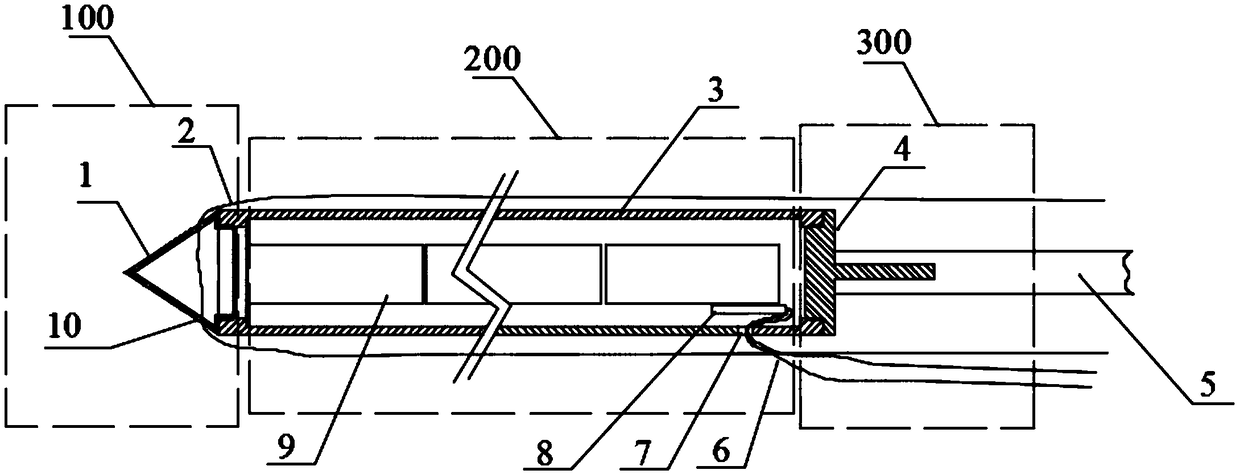
[0038] Such as figure 2 and Figure 5 As shown, a blasting cylinder for deep hole blasting includes a pilot device 100, a charging device 200 and a drug delivery device 300; Two through holes 10, a soft rope 2 passes through the through holes 10, half of the length of the soft rope 2 is greater than the depth of the drilled hole;

[0039] The charge device 200 includes a hollow cylindrical charge cartridge 3, a conical plug 1 is connected to one end of the charge cartridge 3, and a gun rope hole 7 is provided on the charge cartridge 3, and several explosive rolls 9 and A detonator 8 is used for detonation, and the gun rope 6 of the detonator 8 passes through the gun rope hole 7 and extends to the outer end of the borehole; When charging, the explosive rolls 9 are evenly arranged in the charge barrel in turn, and finally the detonator 8 is installed;

[0040] The drug delivery device 300 incl...

Embodiment 3

[0049] The present embodiment is based on the reverse blasting charge mode.

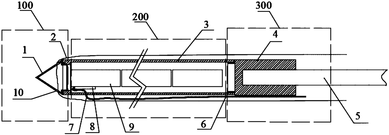
[0050] Such as image 3 and Figure 5 As shown, a blasting cylinder for deep hole blasting includes a pilot device 100, a charging device 200 and a drug delivery device 300; Two through holes 10, a soft rope 2 passes through the through holes 10, half of the length of the soft rope 2 is greater than the depth of the drilled hole;

[0051] The charge device 200 includes a hollow cylindrical charge cartridge 3, a conical plug 1 is connected to one end of the charge cartridge 3, and a gun rope hole 7 is provided on the charge cartridge 3, and several explosive rolls 9 and A detonator 8 for detonation, the gun rope 6 of the detonator 8 passes through the gun rope hole 7 and extends to the outer end of the borehole; the gun rope hole 7 is opened on the side wall of the cartridge 3 near the end of the tapered plug 1, When charging, the detonator 8 is first loaded into the cartridge 3, and then the explo...


PUM


Abstract

The invention discloses a deep hole blasting explosive cartridge. The deep hole blasting explosive cartridge comprises a front guide device, a powder charging device and a powder feeding device. The front guide device is a hollow taper end cap, the side wall of the taper end cap is symmetrically provided with two through holes, an oil wire rope penetrates through the through holes, and half of theoil wire rope is larger than the hole depth of a drill hole. The powder charging device comprises a hollow cylindrical powder charging cylinder, the taper end cap is connected to one end of the powder charging cylinder, the powder charging cylinder is provided with a laryard hole, the powder charging cylinder is internally provided with a plurality of stick dynamites and a detonating detonator, and a laryard of the detonator penetrates through the laryard hole and extends to the outer end of the drill hole. The powder feeding device comprises a tail end cap connected to the other end of the powder charging cylinder, and the other end of the tail end cap is provided with a groove or a protrusion matched with a powder feeding rod. According to the deep hole blasting explosive cartridge, powder charging is convenient and stable, powder can be precisely fed to a preset position, the success rate of explosion of loosening explosive powder is increased, the loosening blasting cost is reduced, and the deep hole blasting explosive cartridge is conveniently taken out when misfire detonation of the explosive powder occurs.

Description

technical field [0001] The invention relates to deep hole blasting equipment, in particular to a blasting cylinder for deep hole blasting, which belongs to the technical field of blasting. Background technique [0002] Deep hole blasting is a blasting technology with a borehole diameter greater than 75mm and a hole depth greater than 5m. Deep hole blasting has the advantages of small drilling volume per unit, low consumption of explosives per unit, high production efficiency, and the convenience of comprehensive mechanized construction for blasting, excavation, and transportation operations. It is widely used in open-pit and underground excavation projects. [0003] The pre-blasting position of deep hole blasting is often located in the depth of long-distance drilling, and the depth of the drilling hole is usually greater than 15m. In order to send the explosives to the blasting site, the existing deep hole blasting technology mostly uses PVC pipes as the filling chamber for...

Claims


Application Information

Patent Timeline
Patent Type & Authority Applications(China)
IPC IPC(8): F42B3/00
CPCF42B3/00
Inventor 杨威路长征王皓林柏泉查伟林明华宋浩然张建国吕有厂
Owner CHINA UNIV OF MINING & TECH
Why Eureka
Try Eureka