Spacecraft sinusoidal vibration test recessing condition formulation method

A sinusoidal vibration and spacecraft technology, applied in the field of spacecraft, can solve the problems of inability to do full-frequency comparison, heavy manual workload, hidden risks, etc., to avoid selective omissions, save waiting time, and optimize the test workflow Effect

Active Publication Date: 2018-12-14
BEIJING INST OF SPACECRAFT SYST ENG
View PDF4 Cites 3 Cited by
  • Summary
  • Abstract
  • Description
  • Claims
  • Application Information

AI Technical Summary

Problems solved by technology

[0008] The whole process involves the interpretation, calculation, estimation and analysis of a large amount of test data. In the past, it was done manually, and the workload was huge, which led to long overtime and waiting for the personnel of the test team at the test site. This is especially true for large-scale spacecraft with a large number of monitoring point channels; and the previous method usually compares several maximum response points, which cannot achieve full-frequency comparison, and the sub-maximum response and partial response are easy to be missed. The determination of the site of concern or stand-alone equipment depends on some human subjective judgments or empirical factors, and the measuring point channels and non-maximum response frequency points that are not identified as the site of concern or stand-alone equipment are selectively ignored
[0009] Therefore, it is difficult to meet the first two criteria mentioned above in a strict sense. This method has a large amount of manual work and is easy to miss, which brings great risks and hidden dangers to the test. Some structures or stand-alone Quality problems such as equipment damage due to over-testing are caused by the shortcomings of this method

Method used


Image

  • Spacecraft sinusoidal vibration test recessing condition formulation method
  • Spacecraft sinusoidal vibration test recessing condition formulation method
  • Spacecraft sinusoidal vibration test recessing condition formulation method

Examples


Embodiment Construction

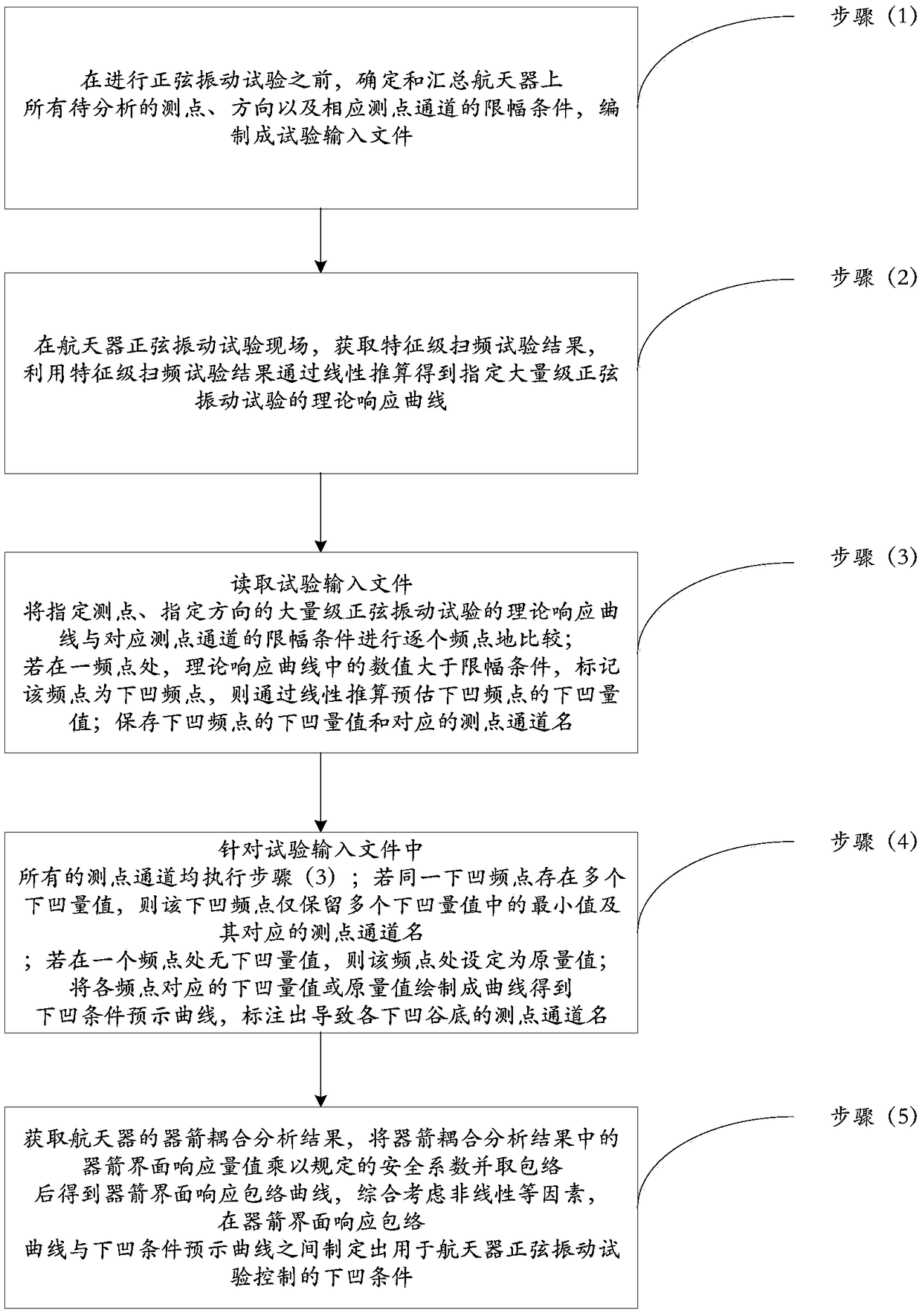
[0034] The present invention will be described in detail below with reference to the drawings and embodiments.

[0035] The invention provides a method for formulating the concave conditions of a spacecraft sinusoidal vibration test, which is strictly based on the concave control criterion of the spacecraft sinusoidal vibration test.

[0036] The sunken control criteria for spacecraft sine vibration test include:

[0037] Criterion 1: In the spacecraft sine vibration test, the maximum strain response of the main structure of the spacecraft shall not be greater than the maximum strain value of the main structure of the spacecraft in the static test.

[0038] Criterion 2: The acceleration response at the critical stand-alone equipment installation position on the spacecraft does not exceed the component-level sinusoidal vibration test conditions specified in the environmental test specification.

[0039] Criterion 3: The input vibration value of the entire spacecraft after the dent is not...


PUM


Abstract

The present invention discloses a spacecraft sinusoidal vibration test recessing condition formulation method which is a rigorous and accurate spacecraft sinusoidal vibration test recessing conditionformulation sequencing method. The method comprises the following steps of: prior to test, determining and collecting all the measurement points to be analyzed, directions, and amplitude limiting conditions of corresponding measurement point channels of a spacecraft; at a test scene, obtaining a feature-level frequency sweeping test result, and performing linear calculation to obtain a theory response curve of an assigned large-scale sinusoidal vibration test; performing comparison of the theory response curve of the large-scale sinusoidal vibration test and the amplitude limiting conditions of corresponding measurement point channels one by one to find frequency points requiring recessing and store low recessed values of the frequency points and corresponding channel names; performing comparison for all the measurement point channels to finally obtain a recessing condition indication curve; and integrally considering non-linear factors, and formulating a recessing condition used for control of the spacecraft sinusoidal vibration test between the response envelope curve and the recessing condition indication curve.

Description

Technical field [0001] The invention relates to the technical field of spacecraft, in particular to a method for formulating concave conditions for a spacecraft sine vibration test. Background technique [0002] The spacecraft must undergo sinusoidal vibration tests in each development stage to assess the rigidity and strength design of the structure, and to obtain the response data of the measuring point channels on the vehicle. In the test, since the resonance frequency of the spacecraft is generally within the test frequency range, it is often necessary to sink the test conditions in order to avoid excessive response. However, it is a tedious and time-consuming process to formulate the sinking conditions on site, usually by manually interpreting the results of the feature-level frequency sweeping test one by one to determine the concerned parts and stand-alone equipment (data processing at the test site is required, which takes a long time and is prone to omissions) And calcu...

Claims


Application Information

Patent Timeline
IPC IPC(8): G01M7/00
CPCG01M7/00
Inventor 李青任德鹏王闯阮剑华
Owner BEIJING INST OF SPACECRAFT SYST ENG
Why Eureka
Try Eureka