Rapid design and optimization method of energy absorbing structure at front end of rail vehicle chassis
A technology of energy-absorbing structure and optimization method, which is applied in the field of rail vehicle collision passive safety analysis and test, and can solve problems such as high design cost, long design cycle, and inability to meet the market rhythm
Pending Publication Date: 2018-12-14
CRRC CHANGCHUN RAILWAY VEHICLES CO LTD
View PDF7 Cites 7 Cited by
- Summary
- Abstract
- Description
- Claims
- Application Information
AI Technical Summary
Problems solved by technology
For a brand-new product, in the scheme design stage, it is usually necessary to carry out hundreds of analysis and calculations to carry out the research and development of the energy-absorbing structure of the chassis. Due to the limitation of computer hardware conditions, a complete
Method used
View moreImage
Smart ImageViewing Examples
Examples
 PUM
 Abstract
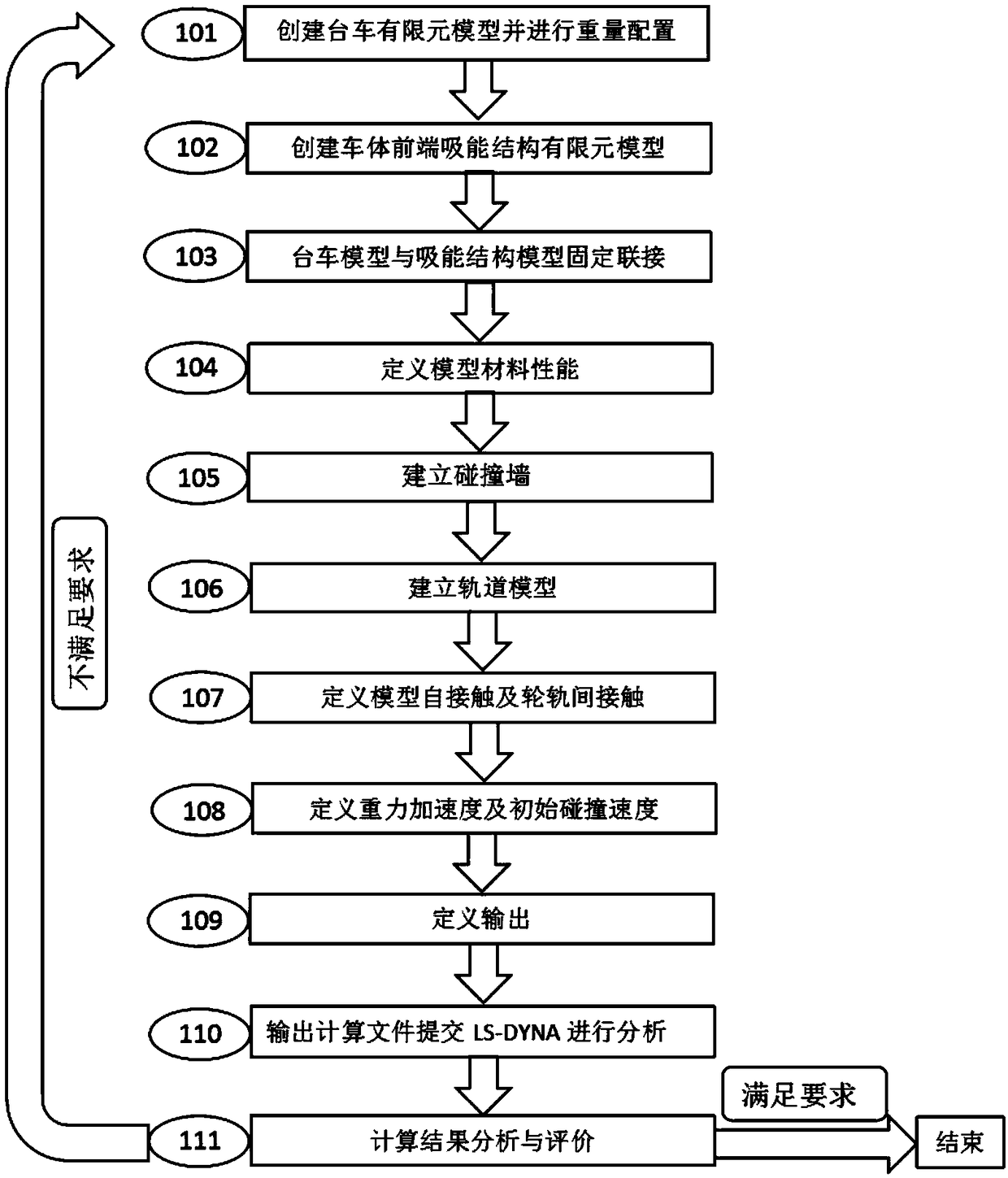
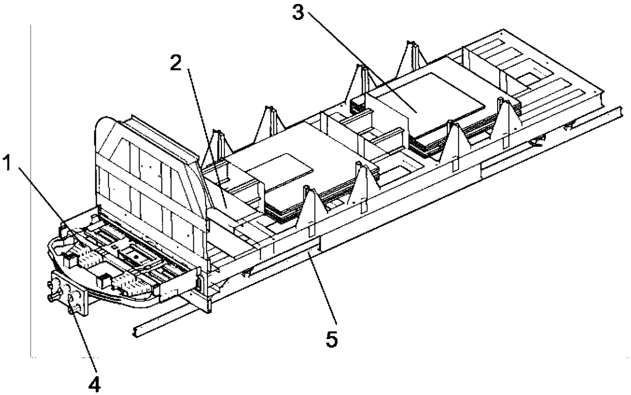
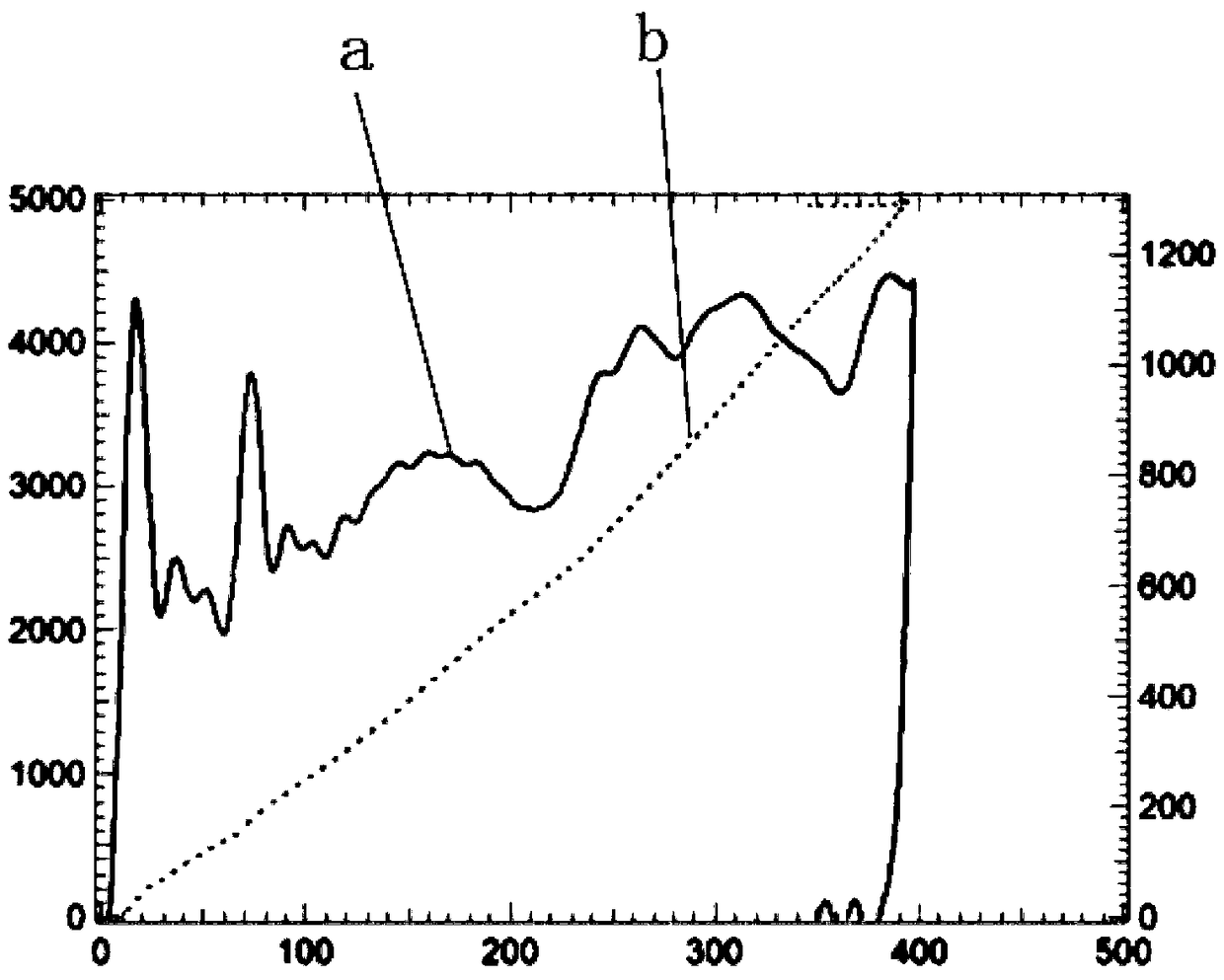
A rapid design and optimization method of an energy absorbing structure at the front end of a rail vehicle chassis includes the steps of establishing a finite element model of a trolley and a finite element model of the energy-absorbing structure of the front end of the car body chassis, and connecting the finite element model of the energy-absorbing structure of the front end of the car body chassis with the finite element model of the trolley as an analysis and calculation model; defining the element types, attributes and material properties of the analysis and calculation model; establishing a finite element model of rigid walls and load cells, and a finite element model of tracks, and arranging an acceleration sensor on the finite element model of the trolley; defining contact relation, acceleration of gravity and initial collision velocity; defining the output information, outputting the calculation file and submit the file to an LS-DYNA platform calculation; performing analysis and judgment according to the calculation results, finishing the analysis if it meets the requirements, otherwise, modifying the structural parameters are modified and performing recalculation. The invention rapidly realizes the analysis and optimization and structure modification of the energy-absorbing structure at the front end of the rail vehicle chassis, the model structure is modified in 4 hours, and the calculation is completed once in 1 hour, which provides the theoretical and experimental technical support for the crashworthiness design of the energy-absorbing structure at the front end of the rail vehicle chassis of the rail vehicle.
Description
technical field [0001] The invention relates to the field of rail vehicle collision passive safety analysis and testing, in particular to a rapid analysis, design and optimization method for an energy-absorbing structure at the front end of a rail vehicle body underframe. technical background [0002] With the improvement of train speed and operating efficiency, people pay more and more attention to the passive safety of train collision, and the passive safety design of collision has become an important part of train design. The occurrence of train collision accidents not only threatens the lives of passengers, but also causes huge economic losses and social impact. Therefore, how to improve the passive safety of trains, protect the lives and property of passengers, and reduce economic losses is worthy of further research. [0003] The key to the crashworthiness of rail vehicles lies in the design of the energy-absorbing structure of the underframe. In China, the simulation...
Claims
Login to View More Application Information
Patent Timeline
 IPC IPC(8): G06F17/50
CPCG06F30/15G06F30/23Y02T10/40
Inventor 刘春艳刘艳文王璐
Owner CRRC CHANGCHUN RAILWAY VEHICLES CO LTD
Features
- R&D
- Intellectual Property
- Life Sciences
- Materials
- Tech Scout
- Unparalleled Data Quality
- Higher Quality Content
- 60% Fewer Hallucinations
Learn More Browse by: Latest US Patents, China's latest patents, Technical Efficacy Thesaurus, Application Domain, Technology Topic, Popular Technical Reports.
© 2025 PatSnap. All rights reserved.Legal|Privacy policy|Modern Slavery Act Transparency Statement|Sitemap|About US| Contact US: help@patsnap.com


