
Pile and soil interaction visual testing device and method

A test device and pile-soil technology, which is applied in foundation structure test, construction, foundation structure engineering, etc., can solve problems such as difficulty in vertical wall-attachment, inconsistency, displacement of soil around piles, etc., and achieve the goal of improving test controllability Effect

Active Publication Date: 2019-06-11
CHONGQING UNIV
View PDF5 Cites 11 Cited by
  • Summary
  • Abstract
  • Description
  • Claims
  • Application Information

AI Technical Summary

Problems solved by technology

However, the simulated amorphous silicon or fused silica sand is quite different from the soil particle properties in the actual project, the actual soil is often in an unsaturated state, and the scale of the model in the transparent soil test is too large, etc. The soil displacement around the pile does not match the actual project
In addition, in the transparent soil test, the breakage of soil particles under the pile-soil interaction is still difficult to measure. It is still difficult to maintain the vertical attachment state of the pile body in the visualization test. The shape of the pile body in the test is too simple and deforms itself. still difficult to measure

Method used


Image

  • Pile and soil interaction visual testing device and method
  • Pile and soil interaction visual testing device and method
  • Pile and soil interaction visual testing device and method

Examples


Embodiment 1

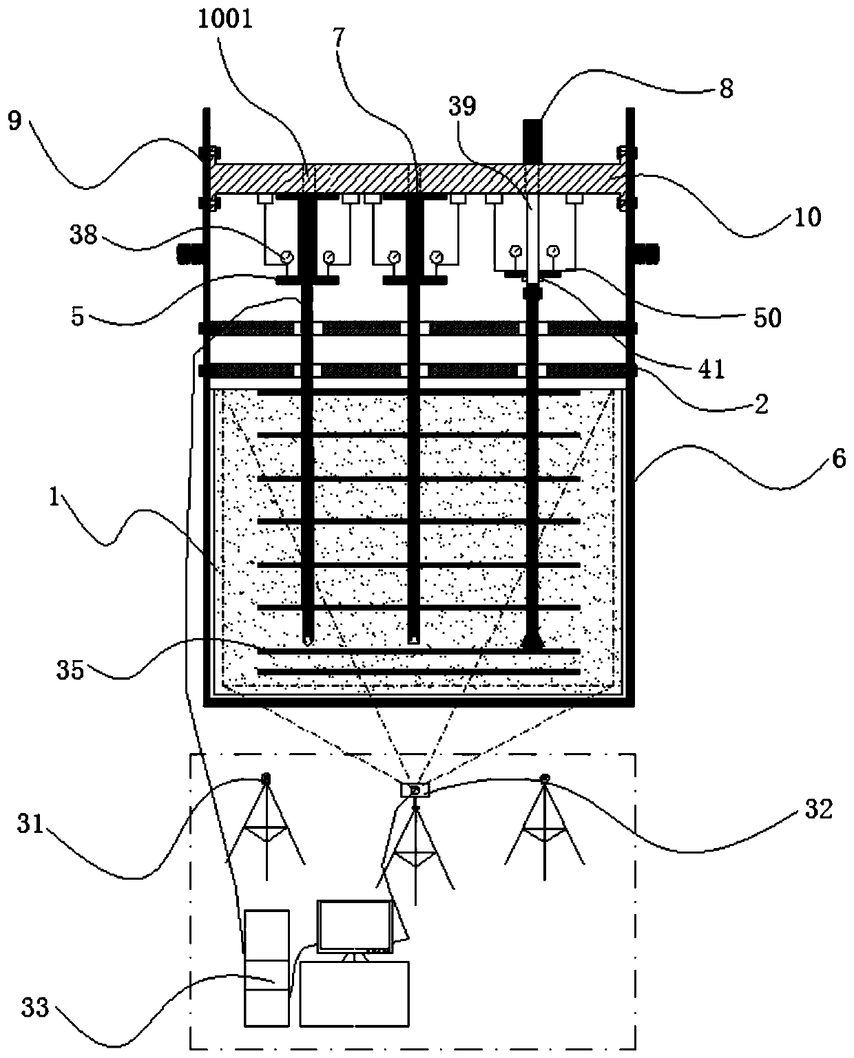
[0069] see figure 1 , this embodiment discloses a pile-soil interaction visualization test device, including a plexiglass box 1, two pile stoppers 2, a box supporting steel frame 6, two movable supports 9, and a movable reaction beam 10 , model half-pile and visualization system.

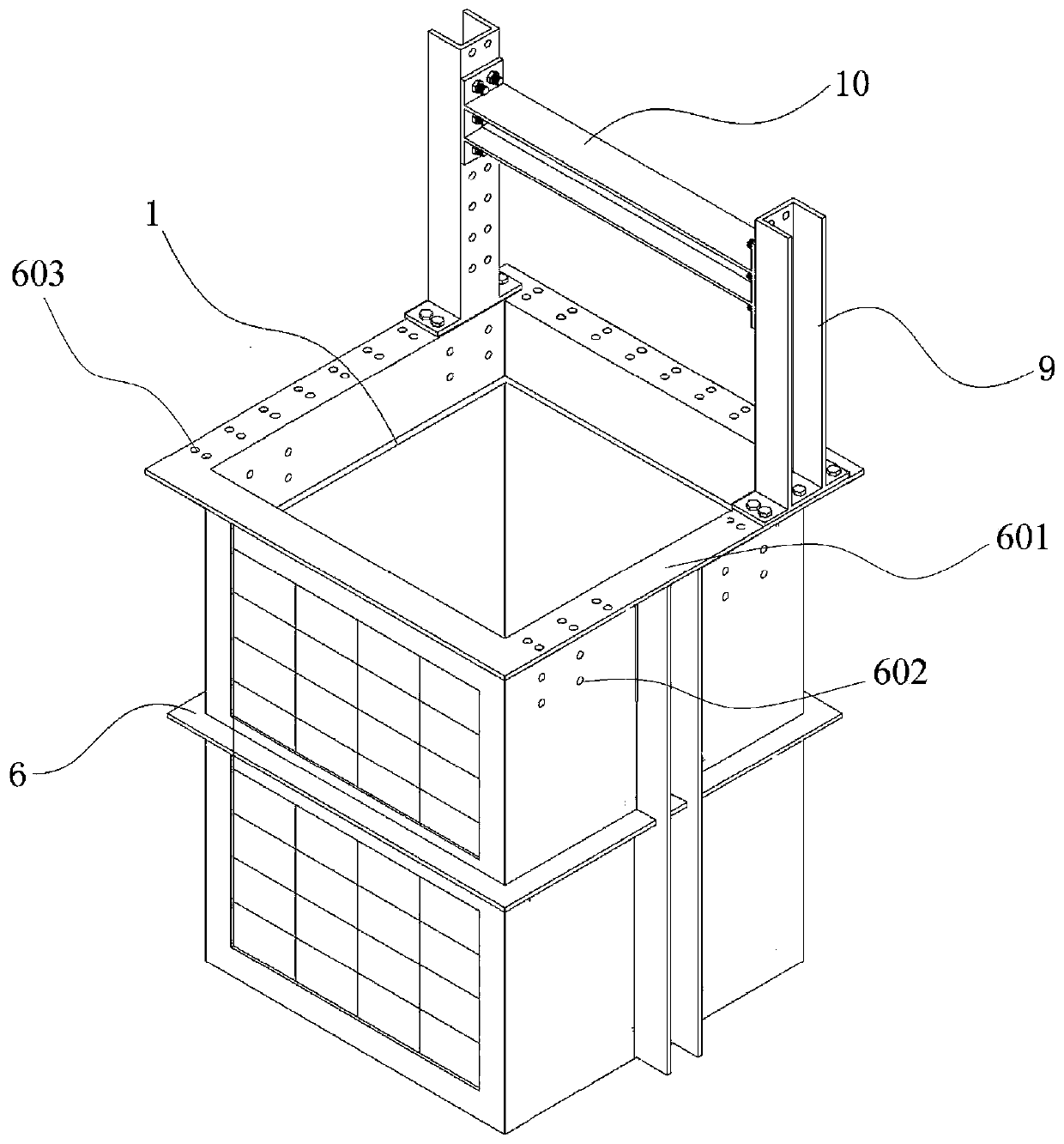
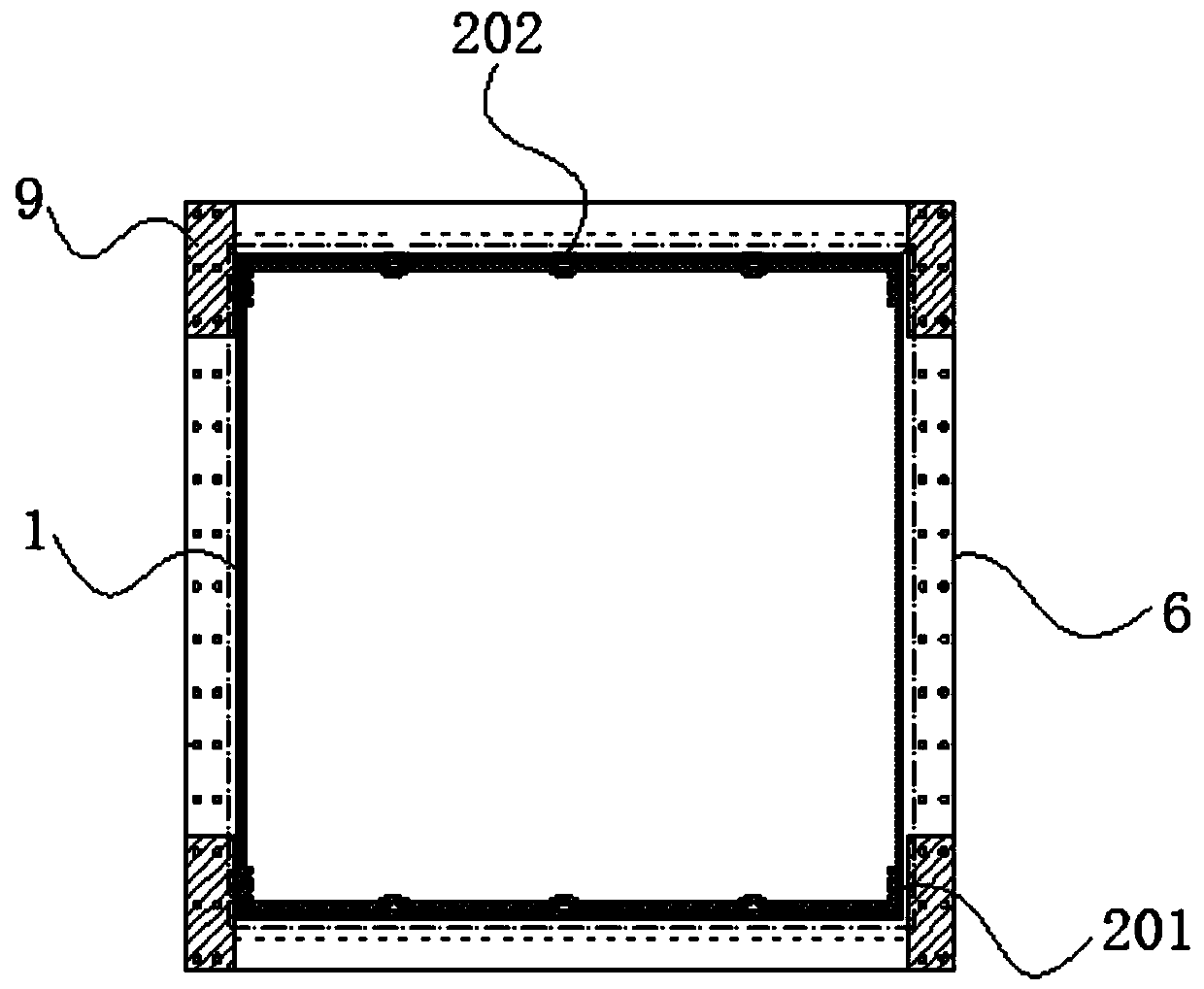
[0070] see figure 2 , the box supporting steel frame 6 is a rectangular box as a whole. The upper end surface of this rectangular box is provided with a top steel plate reinforcing hoop 601 . The plexiglass box 1 is a rectangular box. The plexiglass box 1 is embedded in the inner cavity of the box supporting steel frame 6 . The height difference between the box supporting steel frame 6 and the plexiglass box 1 is 25-35 cm. The inner cavity of the plexiglass box 1 is filled with soil materials. The soil material includes multiple layers of undyed soil particles and layers of colored soil particles 35 arranged at intervals.

[0071] The four side walls of the box supporting steel frame 6 are t...

Embodiment 2

[0081] This embodiment discloses a pile-soil interaction visualization test device, which includes a plexiglass box 1, a plurality of pile stoppers 2, a box supporting steel frame 6, two movable supports 9, a movable reaction beam 10, Model semi-pile and visualization system.

[0082] The box supporting steel frame 6 is a rectangular box as a whole. The upper end surface of this rectangular box is provided with a top steel plate reinforcing hoop 601 . The plexiglass box 1 is a rectangular box. The plexiglass box 1 is embedded in the inner cavity of the box supporting steel frame 6 . The height difference between the box supporting steel frame 6 and the plexiglass box 1 is 25-35 cm. The inner cavity of the plexiglass box 1 is filled with soil materials. The soil material includes several layers of undyed soil particle layers and colored soil particle layers 35 arranged at intervals.

[0083] The four side walls of the box supporting steel frame 6 are the first side wall, t...

Embodiment 3

[0090] This embodiment discloses a kind of test method about the test device described in embodiment 1 or 2, comprising the following steps:

[0091] 1) According to the simulated working conditions, select the model half pile with the corresponding pipe diameter, and arrange the pressure sensor 23 and the strain gauge 29 as required.

[0092] 2) According to the simulated working conditions, select soil granular materials and corresponding industrial dyes.

[0093] 3) Sieve the soil particle material into multiple particle size groups, dye the soil particle materials of different particle size groups into different colors for calibration, and obtain dyed soil particles with different particle sizes and different colors after drying.

[0094] 4) Evenly mixing the dyed soil particle material according to the particle size gradation ratio to prepare a mixed soil particle material.

[0095] 5) Clean up the plexiglass box 1. Combined with the working conditions, the colored soil...


PUM


Abstract

The invention provides a pile and soil interaction visual testing device and method. The testing box device comprises a testing box, pile body limiters, model piles, a visual system and a pile body loading and measuring device; and an organic glass box body is embedded in an inner cavity of a box body supporting steel frame, and the detachable pile body limiters are located on the upper part of the testing box so as to ensure that pile bodies are vertically and tightly attached to the inner wall of the box. A matched pile and soil interaction study in soil particle layers for dyeing of the various model semi-piles is developed; the arranged visual system and a modern image processing and analysis technology are combined, and thus soil body interior detail information such as the dynamic stress, deformation, displacement, the soil body porosity and soil particle crushing in the whole process of pile and soil interaction is revealed; and according to the device, the pile-soil layer effect in the experimental study macroscopic level and the pile-soil particle effect in the finely microcosmic level are combined, various experimental study working conditions can be simulated, and the device is low in weight, good in part disassembly, and clear in acting force of structures and parts.

Description

technical field [0001] The invention relates to the technical field of foundation engineering, in particular to a pile-soil interaction visualization test device and a test method thereof. Background technique [0002] In civil engineering foundation treatment, problems such as insufficient bearing capacity and stability, compression, uneven settlement and liquefaction of the foundation are often faced. As one of the most commonly used methods to deal with bad foundations, pile foundation is widely used in various engineering constructions. However, under the vertical load of the pile foundation, the pile and the soil particles around the pile interact to bear the load of the superstructure together. It is estimated that the project cost has been greatly increased. [0003] The pile-soil interaction law mainly includes two aspects: the pile foundation and the soil around the pile. The pile foundation is generally made of relatively uniform and high-strength concrete materi...

Claims


Application Information

Patent Timeline
Patent Type & Authority Applications(China)
IPC IPC(8): E02D33/00
Inventor 彭宇丁选明邓玮婷崔春义邓鑫李佳
Owner CHONGQING UNIV
Learn More