Manual image measuring instrument

An image measuring instrument and image measuring technology, applied in the field of measuring instruments, can solve problems such as inability to adjust, no adjustment device, and large adjustment resistance, and achieve the effects of convenient adjustment operation, reduced measurement error, and guaranteed measurement accuracy

Inactive Publication Date: 2006-05-24
东莞市升力智能科技有限公司
View PDF0 Cites 14 Cited by
  • Summary
  • Abstract
  • Description
  • Claims
  • Application Information

AI Technical Summary

Problems solved by technology

However, at present, the connection between the CCD and the lens of the image measuring machine is connected by c-mount, and the center of the CCD and the center of the lens cannot be adjusted; Whether it is perpendicular to the workbench is completely guaranteed by machining, and cannot be adjusted. It is difficult to guarantee the perpendicularity of the lens and the workbench
Due to the above two reasons, it is difficult to ensure the accuracy of the measurement during the measurement process
At the same time, in the prior art, the movement of the Z axis is adjusted by the handle installed on the Z axis, so it is very inconvenient to adjust during the measurement process. In addition, there is no counterweight device in the structure of the prior art, so the resistance of the adjustment Larger; there is no adjustment device between the base and the support base and the bottom of the support base, which also has a great impact on the levelness of the workbench

Method used


Image

  • Manual image measuring instrument
  • Manual image measuring instrument
  • Manual image measuring instrument

Examples


Embodiment Construction

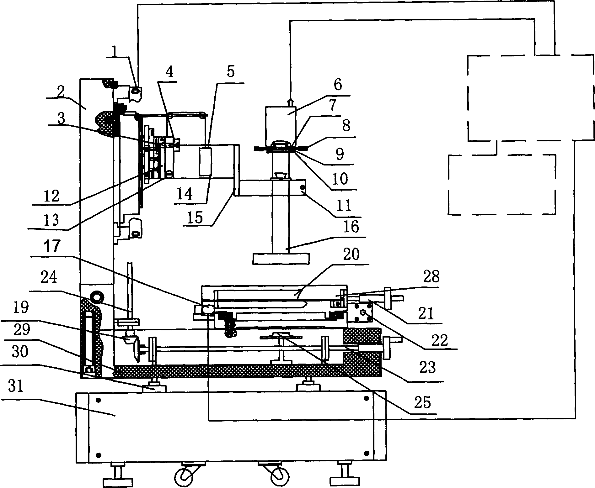
[0017] A preferred embodiment of the present invention is mainly composed of the following parts: imaging system (including: zoom lens, CCD camera and image acquisition card, etc.), lighting system (light source, light source controller), motion system (Z axis / X, Y Workbench), software and auxiliary parts (support seat, adjustment seat, grating ruler, etc.).

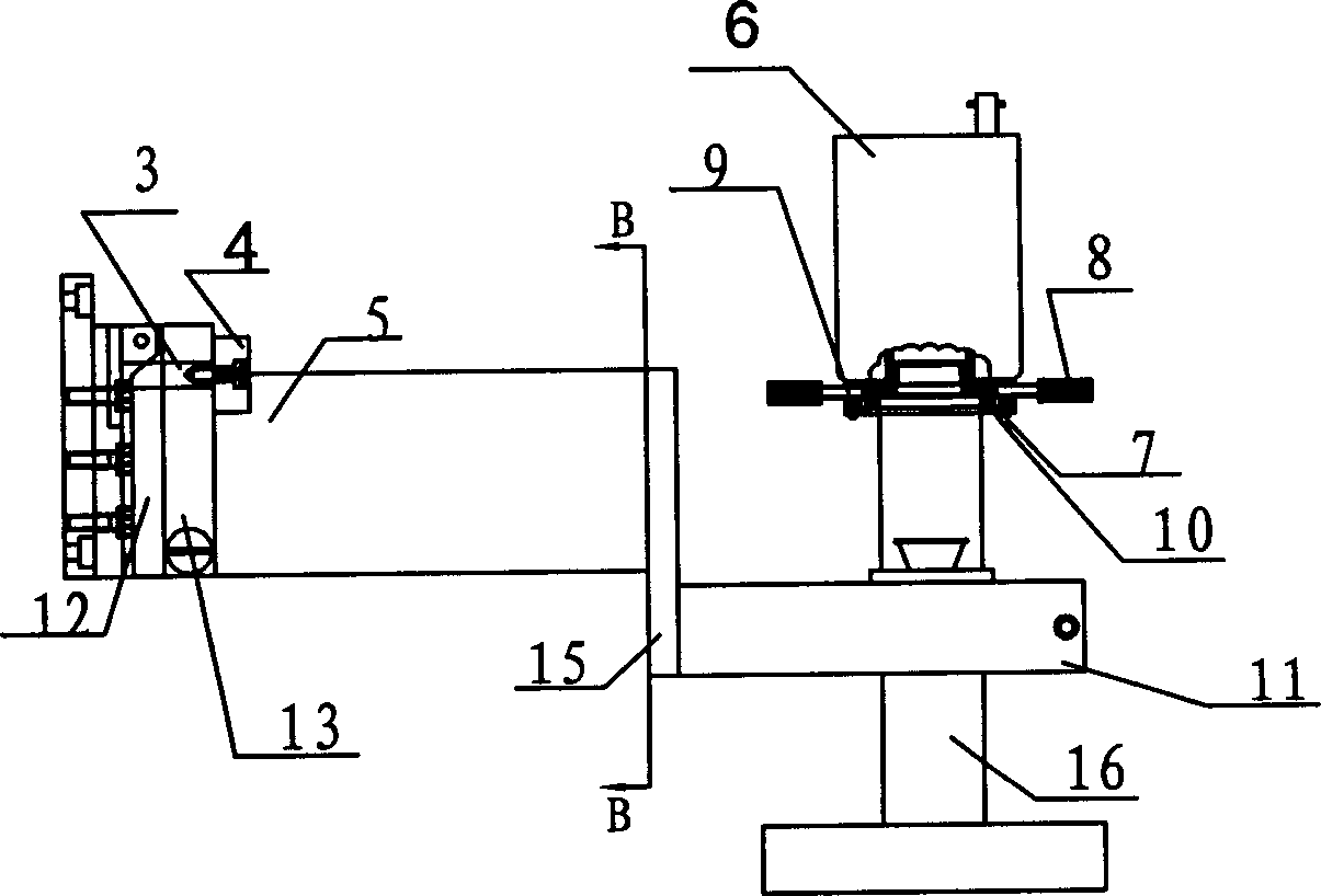
[0018] See attached figure 1 As shown: the column 1 and the base 29 are positioned by positioning pins and connected by bolts to form the supporting components of the entire manual image measurement system. The moving parts in the Z-axis direction are fixed on the column by bolts. The CCD camera 6 and the zoom lens 16 are connected through the adjustment device between them and fixed on the camera and the microscope fixed adjustment device through the lens clamp 11, while the camera and the microscope fixed adjustment device are fixed on the z-axis connecting plate with bolts through the connecting base plate superior....


PUM


Abstract

Through adjusting gear, CCD camera and zoom lens are connected; and through lens clamp, CCD camera and zoom lens are fixed on fixation adjustment device for camera and microscope. Through bolt, the camera and microscope is connected to the connection base plate in z-axis. The connection base plate in z-axis is fixed on a nut in z-axis. Through screw thread, transmission shaft in z-axis is connected to the nut in z-axis. Through bearing seats, the fixed transmission shaft is connected to horizontal transmission shaft through helical beval gear. Rotating handwheel installed on the horizontal transmission shaft makes transmission shaft in z-axis rotate so that nut and the connection base plate are moved along guide rail in z direction up and down.

Description

Technical field: [0001] The invention relates to the technical field of measuring instruments, in particular to an easily adjustable high-precision manual image measuring instrument. Background technique: [0002] With the continuous improvement of the level of industrial processing and manufacturing, the size of the products to be tested is constantly decreasing, so new requirements are put forward for the detection methods. The previous detection methods such as manual detection can no longer meet the new detection requirements. Computer vision inspection technology has been widely used in industrial inspection because of its good flexibility, non-contact, fast and efficient characteristics. In computer vision inspection, the adjustment and calibration of hardware is very important, among which the adjustment of CCD and lens is one of the keys. Before measurement, it is necessary to ensure that the center of CCD and the center of the lens are on the same axis, so this adju...

Claims


Application Information

Patent Timeline
Patent Type & Authority Applications(China)
IPC IPC(8): G01B11/00G01B11/02
Inventor 李迪张舞杰叶锋
Owner 东莞市升力智能科技有限公司
Why Eureka
Try Eureka