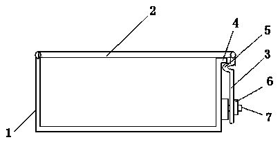
Cable bridge cover plate fixing structure
A technology for cable trays and fixed structures, applied in the direction of electrical components, etc., can solve the problems that operators cannot construct, cover plates cannot be fixed, and the space is too small to accommodate operators, so as to avoid the effect of not being able to fix
- Summary
- Abstract
- Description
- Claims
- Application Information
AI Technical Summary
Problems solved by technology
Method used
Image
Examples
Embodiment Construction
[0013] The present invention will be further described below in conjunction with the accompanying drawings. The following examples are only used to illustrate the technical solution of the present invention more clearly, but not to limit the protection scope of the present invention.
[0014] Such as figure 1 As shown, the fixed structure of the cable bridge cover plate includes a bridge frame 1 and a cover plate 2, and also includes a fixed rod 3. The top of the right side of the bridge frame 1 is provided with an outward protrusion 4, and the bottom end of the right side of the bridge frame 1 is provided with a Screw 7, the left end of cover plate 2 is hinged with the left side of bridge frame 1, the right end of cover plate 2 is hinged with the top of fixed rod 3, the length of fixed rod 3 is less than the length of the side of bridge frame 1, fixed rod 3 is arranged on the shaft near the top There is an arch 5 that protrudes to the left, and the bottom end of the fixed ro...
PUM
 Abstract
Description
Claims
Application Information
 - R&D
- Intellectual Property
- Life Sciences
- Materials
- Tech Scout
- Unparalleled Data Quality
- Higher Quality Content
- 60% Fewer Hallucinations
Browse by: Latest US Patents, China's latest patents, Technical Efficacy Thesaurus, Application Domain, Technology Topic, Popular Technical Reports.
© 2025 PatSnap. All rights reserved.Legal|Privacy policy|Modern Slavery Act Transparency Statement|Sitemap|About US| Contact US: help@patsnap.com

