Molding machine for factories

A technology of molding machines and factories, applied in the parts of molding machines, casting equipment, manufacturing tools, etc., can solve problems such as low efficiency

Active Publication Date: 2018-12-18
浙江中杭水泵股份有限公司
View PDF6 Cites 2 Cited by
  • Summary
  • Abstract
  • Description
  • Claims
  • Application Information

AI Technical Summary

Problems solved by technology

[0002] For example, the patent number is CN201610247180.2, a boxed molding machine for green mold sand, including a molding frame. The molding machine box-entry manipulator is installed on the box-out side; the box-out side of the molding machine frame corresponds to the box-incoming end of the box-combining conveyor chain; the molding machine workbench is installed inside the mold

Method used


Image

  • Molding machine for factories
  • Molding machine for factories
  • Molding machine for factories

Examples


Example Embodiment

Specific implementation mode one:

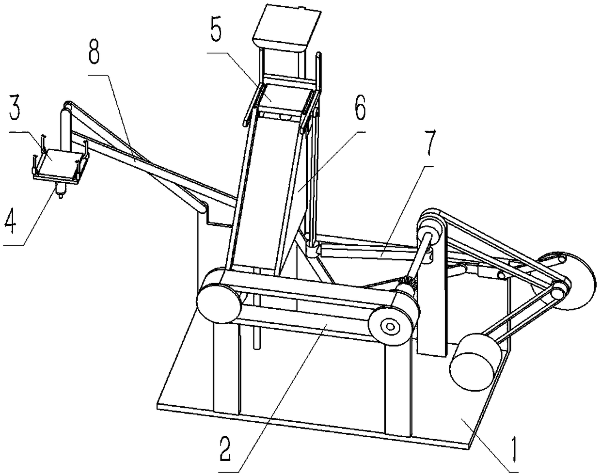
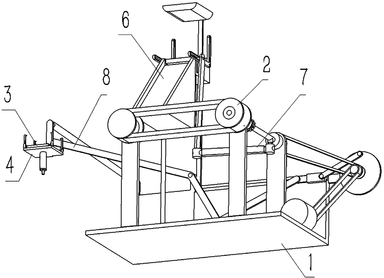
[0039] Combine below Figure 1-19 Describe this embodiment, a factory-used molding machine, including an underframe assembly 1, a conveyor belt 2, a model fixing plate 3, a model cover plate 4, a film lifter 5, a slideway 6, a sliding link 7 and a transmission link 8. The conveyor belt 2 is fixedly connected to the front end of the chassis assembly 1, the model fixing plate 3 is connected to the right end of the chassis assembly 1, the model fixing plate 3 is slidably connected to the middle end of the model sleeve plate 4, and the film lifter 5 is fixedly connected to the middle end of the upper end surface of the chassis assembly 1, the upper end of the slideway 6 is fixedly connected to the film lifter 5, the left end of the sliding link 7 is fixedly connected to the film lifter 5, and the right end of the slide link 7 Slidingly connected to the right end of the upper end surface of the underframe assembly 1, the left end of the transmiss...

Example Embodiment

Specific implementation mode two:

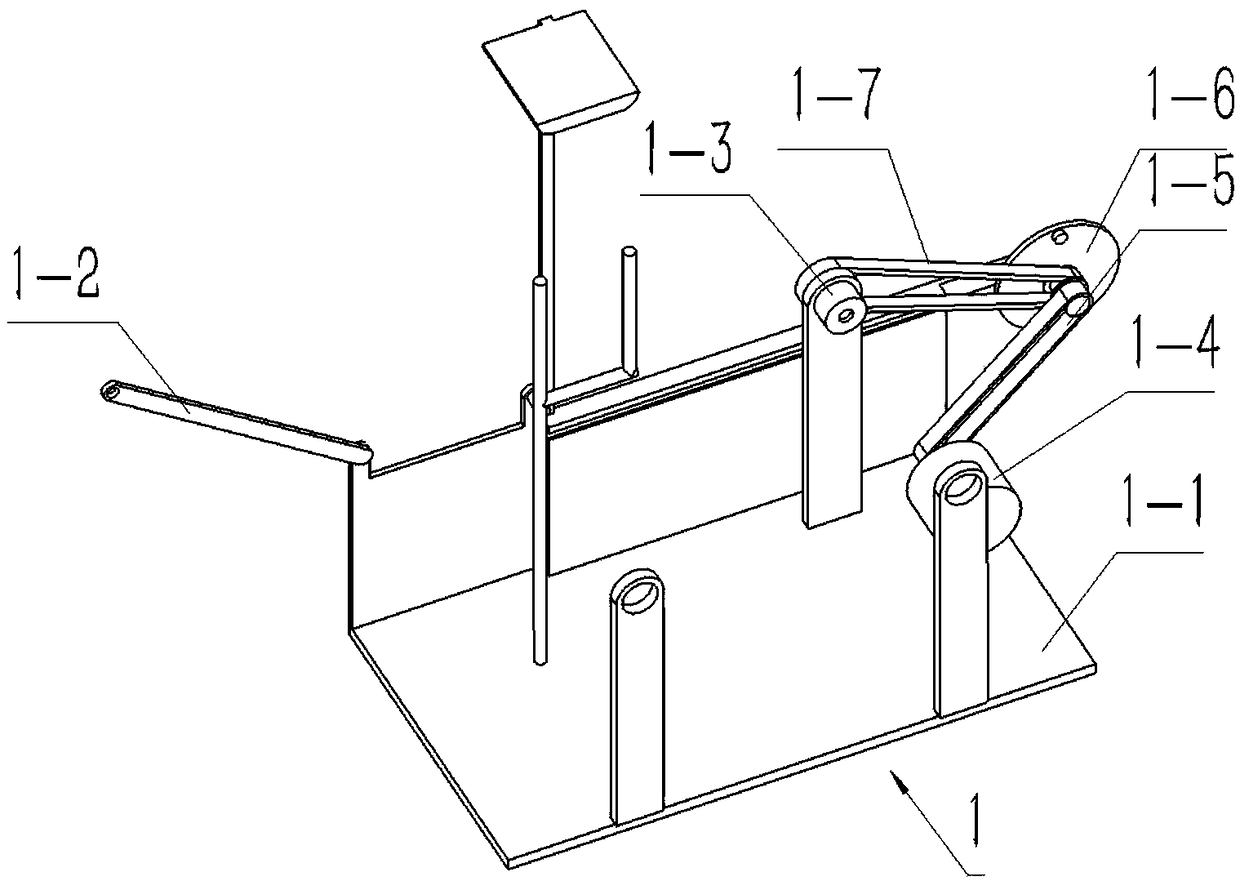
[0040] Combine below Figure 1-19 Describe this embodiment, this embodiment will further explain the first embodiment, the chassis assembly 1 includes a bottom plate 1-1, a left connecting rod 1-2, a gear sleeve rod 1-3, a motor 1-4, an input synchronous Belt 1-5, rotatable cam 1-6, transmission timing belt 1-7, bracket Ⅰ1-8, bracket Ⅱ1-9, back plate 1-10, right support rod 1-11, trapezoidal chute 1-12, Rear support rod 1-13, upper limit boss 1-14, hinged terminal I1-15, hinged terminal II1-16 and mid-end bracket 1-17, gear sleeve rod 1-3 including gear sleeve rod body 1- 3-1. The sliding hole 1-3-2 of the gear sleeve rod and a plurality of internal teeth Ⅰ1-3-3, the inner end of the gear sleeve rod body 1-3-1 is hollowed out, and the sliding hole 1-3-2 of the gear sleeve rod is set At the front end of the gear sleeve rod body 1-3-1, a plurality of internal teeth I1-3-3 are uniformly arranged on the front end of the inner wall of the gear s...

Example Embodiment

Specific implementation mode three:

[0042] Combine below Figure 1-19 Describe this embodiment, this embodiment will further explain the second embodiment, the conveyor belt 2 includes a conveyor belt body 2-1, a left roller 2-2, a right roller 2-3 and a fixed shaft 2-4 , the fixed shaft 2-4 includes a fixed shaft body 2-4-1, an inner sliding hole 2-4-2 and a plurality of internal teeth II 2-4-3, and the inner sliding hole 2-4-2 is arranged on the fixed shaft body 2-4-2. At the inner end of 4-1, a plurality of internal teeth II 2-4-3 are evenly arranged on the rear end of the fixed shaft body 2-4-1, and the front end of the fixed shaft body 2-4-1 is fixedly connected to the right side roller 2- 3, the left and right ends of the conveyor belt body 2-1 are connected to the left roller 2-2 and the right roller 2-3 with interference fit respectively, and the left roller 2-2 is rotatably connected to the bracket II 1-9 , the body of the fixed shaft 2-4-1 is rotatably connected t...


PUM


Abstract

The invention relates to a molding machine, in particular to a molding machine for factories. The molding machine for the factories can automatically convey model sandboxes, manual conveying is not required, and efficiency can be improved. The molding machine for the factories comprises a bottom bracket combination body, a conveying belt, a model fixing plate, a model sleeve plate, a demolding machine, a slide, sliding connecting rods and transmission connecting rods. A hinge end I can facilitate hinge connection of a left connecting rod. The left connecting rod can be conveniently connected to a hinge end II. A supporting bracket I and a supporting bracket II can facilitate rotating connection of a left roller and a fixed rotating shaft body. A gear sleeve rod body can be conveniently rotatably connected to a rear supporting rod. A back plate can facilitate fixed connection of the hinge end I and the hinge end II. The back plate is conveniently provided with a trapezoid sliding groove. The left roller and a right roller can be conveniently connected to the left and right ends of a conveying belt body in an interference-fit mode. The fixed rotating shaft body can be conveniently slidably connected with the right roller. An inner sliding hole can facilitate sliding connection of a sliding right connecting rod.

Description

technical field [0001] The present invention relates to a molding machine, more specifically a molding machine for factory use. Background technique [0002] For example, the patent number is CN201610247180.2, a boxed molding machine for green mold sand, including a molding frame. The molding machine box-entry manipulator is installed on the box-out side; the box-out side of the molding machine frame corresponds to the box-incoming end of the box-combining conveyor chain; the molding machine workbench is installed inside the molding machine frame, and the outside of the molding machine frame The sand shooting machine is installed, and the sand shooting port of the sand shooting machine corresponds to the workbench of the molding machine, but the disadvantage of this invention is that there is no way to automatically transport the model sandbox, and manual handling is required, and the efficiency is low. Contents of the invention [0003] The purpose of the present inventi...

Claims


Application Information

Patent Timeline
IPC IPC(8): B22C19/00
CPCB22C19/00
Inventor 侯莉芝
Owner 浙江中杭水泵股份有限公司
Why Eureka
Try Eureka