Supercharge Your Innovation With Domain-Expert AI Agents!

A raw material mixing device for cement production

A technology for mixing devices and raw materials, which is applied in cement mixing devices, mixing operation control, clay preparation devices, etc., can solve problems such as unsatisfactory mixing effect, mixing dead angle, affecting mixing effect, etc. , good mixing effect

Active Publication Date: 2020-08-21
商洛尧柏秀山水泥有限公司
View PDF1 Cites 0 Cited by
  • Summary
  • Abstract
  • Description
  • Claims
  • Application Information

AI Technical Summary

Problems solved by technology

[0003] Chinese patent CN205766851U discloses a cement raw material mixer, which includes a feeding tube, a barrel, a screw shaft, a stirring plate, a motor and a bracket, etc., the feeding tube is located at the upper end of the barrel, and the barrel is arranged obliquely on the bracket , the screw shaft is connected to the barrel through bearings, the stirring blades are arranged on the screw shaft in an alternate shape, the motor is located on the bracket, the screw shaft is connected to the motor shaft through a transmission belt, and the lower end of the barrel is provided with Outlet, there are at least two feeding ports above the feeding barrel, and a baffle is provided in the middle of the feeding pipe, but it has the following disadvantages: first, it cannot realize the shaking and moving of the feeding barrel, and thus cannot drive its internal The full mixing of the raw materials depends on the gravity of the raw materials to move downward in the barrel, and the mixing effect is not ideal; secondly, from the attached drawings, it can be seen that there is a gap between the stirring plate and the barrel, so there is a phenomenon of mixing dead angle, which makes Some raw materials cannot be mixed, which affects the effect of raw material mixing; finally, the driving method for mixing is only through the motor, and the driving method is single, which affects the overall mixing effect

Method used


Image

  • A raw material mixing device for cement production
  • A raw material mixing device for cement production
  • A raw material mixing device for cement production

Examples


Embodiment Construction

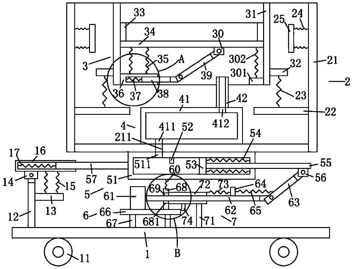
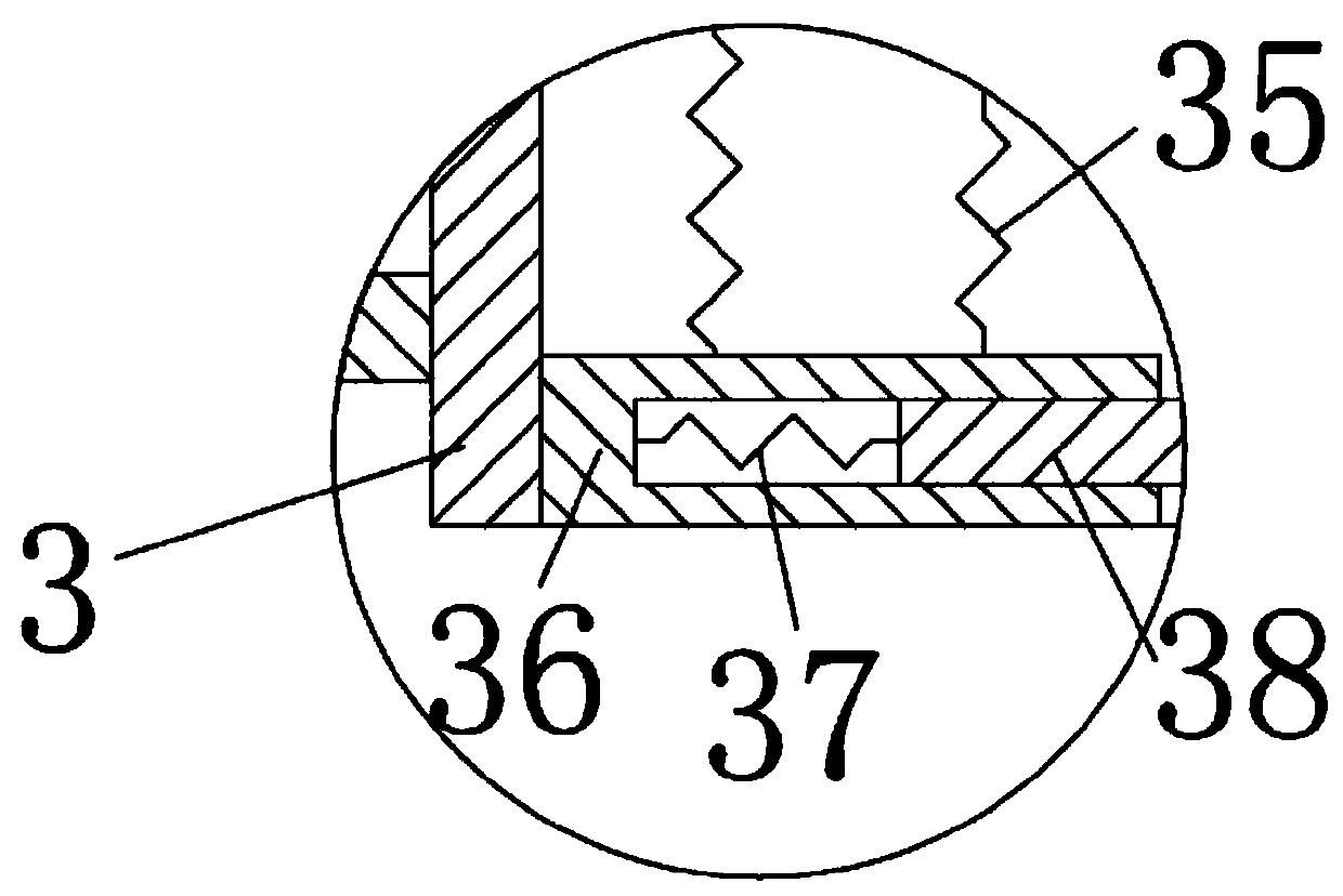
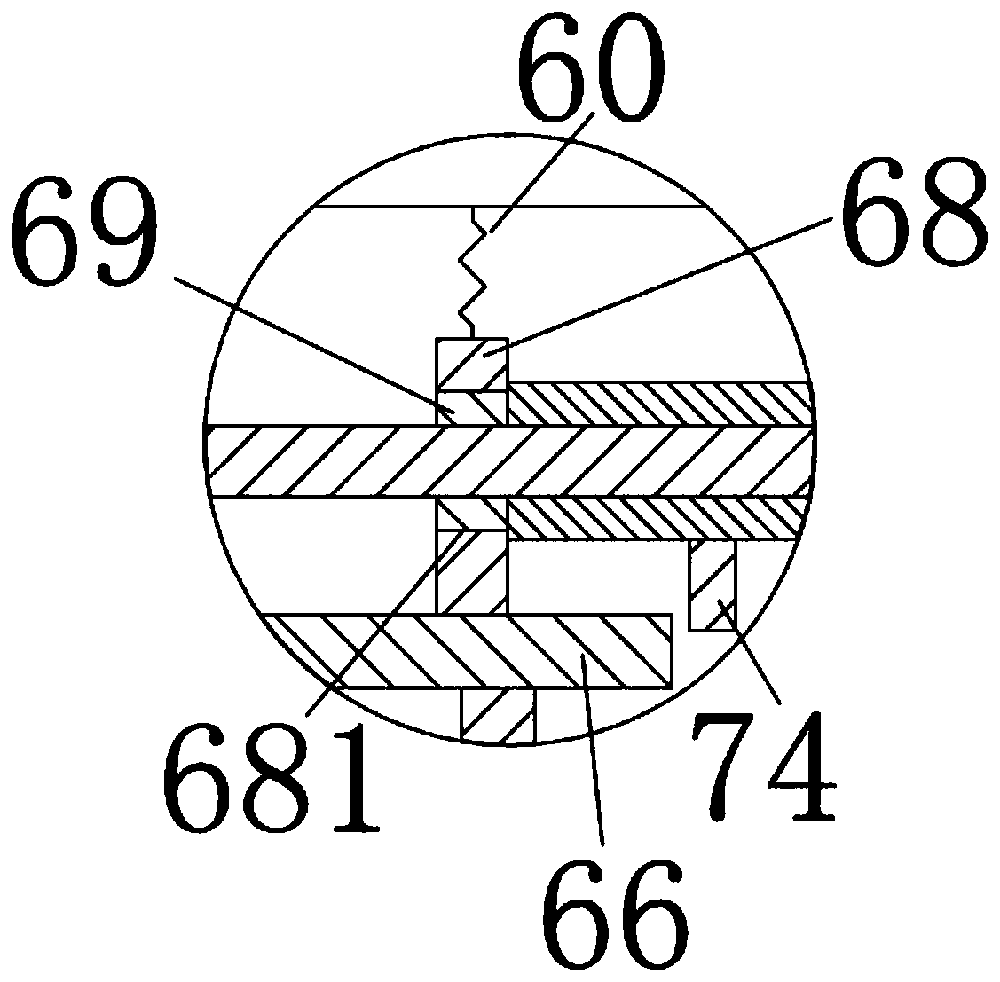
[0015] Such as Figure 1 to Figure 3 As shown, the raw material mixing device for cement production of the present invention includes a bottom plate 1, an outer frame device 2 positioned above the bottom plate 1, an inner frame device 3 accommodated in the outer frame device 2, and an inner frame device 3 located below the inner frame device 3. The air injection device 4, the connecting frame device 5 arranged under the outer frame device 2, the electric cylinder device 6 arranged above the bottom plate 1, and the limiting device 7 arranged on the electric cylinder device 6.

[0016] Such as Figure 1 to Figure 3 As shown, the base plate 1 is provided with several universal wheels 11 below it, a first support rod 12 arranged above the base plate 1, and a first fixed rod arranged on the right side of the first support rod 12 13. The first connecting block 14 arranged above the first support rod 12, the first springs 15 arranged above the first fixed rod 13, the first positioni...


PUM


Abstract

The invention discloses a raw material mixing device for cement production. The raw material mixing device comprises a bottom plate (1), an outer frame device (2) located above the bottom plate (1), an inner frame device (3) contained in the outer frame device (2), an air jet device (4) located below the inner frame device (3), a connection box device (5) arranged below the outer frame device (2),an electric cylinder device (6) arranged above the bottom plate (1), and a limiting device (7) arranged on the electric cylinder device (6). Raw materials can be fully and effectively mixed; the mixing effect is good; and an inner frame can move left and right continuously, then the raw materials in the inner frame can be driven to move left and right continuously and can be driven to move up anddown continuously at the same time, the outer frame can be inclined periodically in the left and right moving process, and then the raw materials can be driven to move left and right fully, so that aphenomenon of a mixing dead angle is prevented.

Description

technical field [0001] The invention relates to the technical field of cement production, in particular to a raw material mixing device for cement production. Background technique [0002] Cement refers to powdery hydraulic inorganic gelling materials. Cement is mixed with water to form a slurry, which can harden in the air or better harden in water, and can firmly bond sand, stone and other materials together. In the cement production process, various raw materials need to be mixed in order to prepare other mixed materials that are convenient to use. [0003] Chinese patent CN205766851U discloses a cement raw material mixer, which includes a feeding tube, a barrel, a screw shaft, a stirring plate, a motor and a bracket, etc., the feeding tube is located at the upper end of the barrel, and the barrel is arranged obliquely on the bracket , the screw shaft is connected to the barrel through bearings, the stirring blades are arranged on the screw shaft in an alternate shape, ...

Claims


Application Information

Patent Timeline
Patent Type & Authority Patents(China)
IPC IPC(8): B28C9/04B28C5/48
CPCB28C5/48B28C9/04
Inventor 张馨元
Owner 商洛尧柏秀山水泥有限公司
Features
  • R&D
  • Intellectual Property
  • Life Sciences
  • Materials
  • Tech Scout
  • Unparalleled Data Quality
  • Higher Quality Content
  • 60% Fewer Hallucinations
Learn More