Injection mold with automatic waste discharging function

An injection mold and waste removal technology, applied in the field of injection molding machines, can solve the problems of a lot of time wasted, waste removal is more troublesome, and the production slope of the workpiece is low.

Active Publication Date: 2018-12-18
SHENZHEN CARES PLASTIC ELECTRONICS
View PDF9 Cites 3 Cited by
  • Summary
  • Abstract
  • Description
  • Claims
  • Application Information

AI Technical Summary

Problems solved by technology

[0004] The above-mentioned injection mold uses two gates for injection, and then the two pouring gates are brought together to form one pouring gate to pour the workpiece to avoid product burnt. The above-mentioned injection mold can also be used for Injection molding of plastic products, but in the injection molding process, due to the use of two pouring ports, which are connected internally, two runners converge together, and the pouring cannot be completed only by using the horizontal extrusion rod in the above-mentioned injection mold. The removal of waste in the runner leads to more troublesome removal of waste in the runner when the workpiece is produced later, and a lot of time wasted, which in turn leads to a low production slope of the workpiece

Method used


Image

  • Injection mold with automatic waste discharging function
  • Injection mold with automatic waste discharging function
  • Injection mold with automatic waste discharging function

Examples


Embodiment

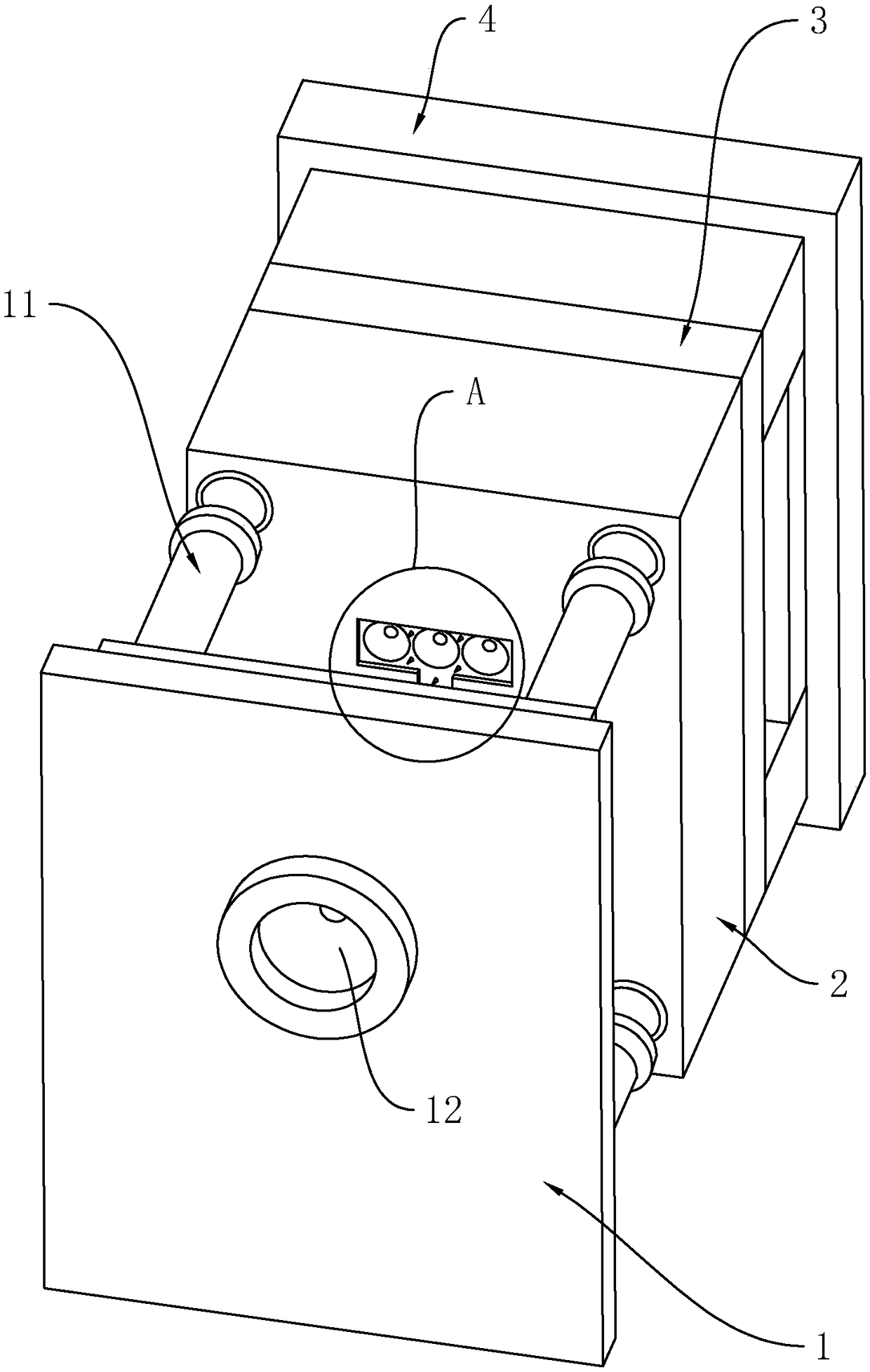
[0044] Embodiment: a kind of injection mold that takes off waste material automatically, combines figure 1 , including a front base plate 1, a front formwork 2, a rear formwork 3 and a rear base plate 4 arranged in sequence.

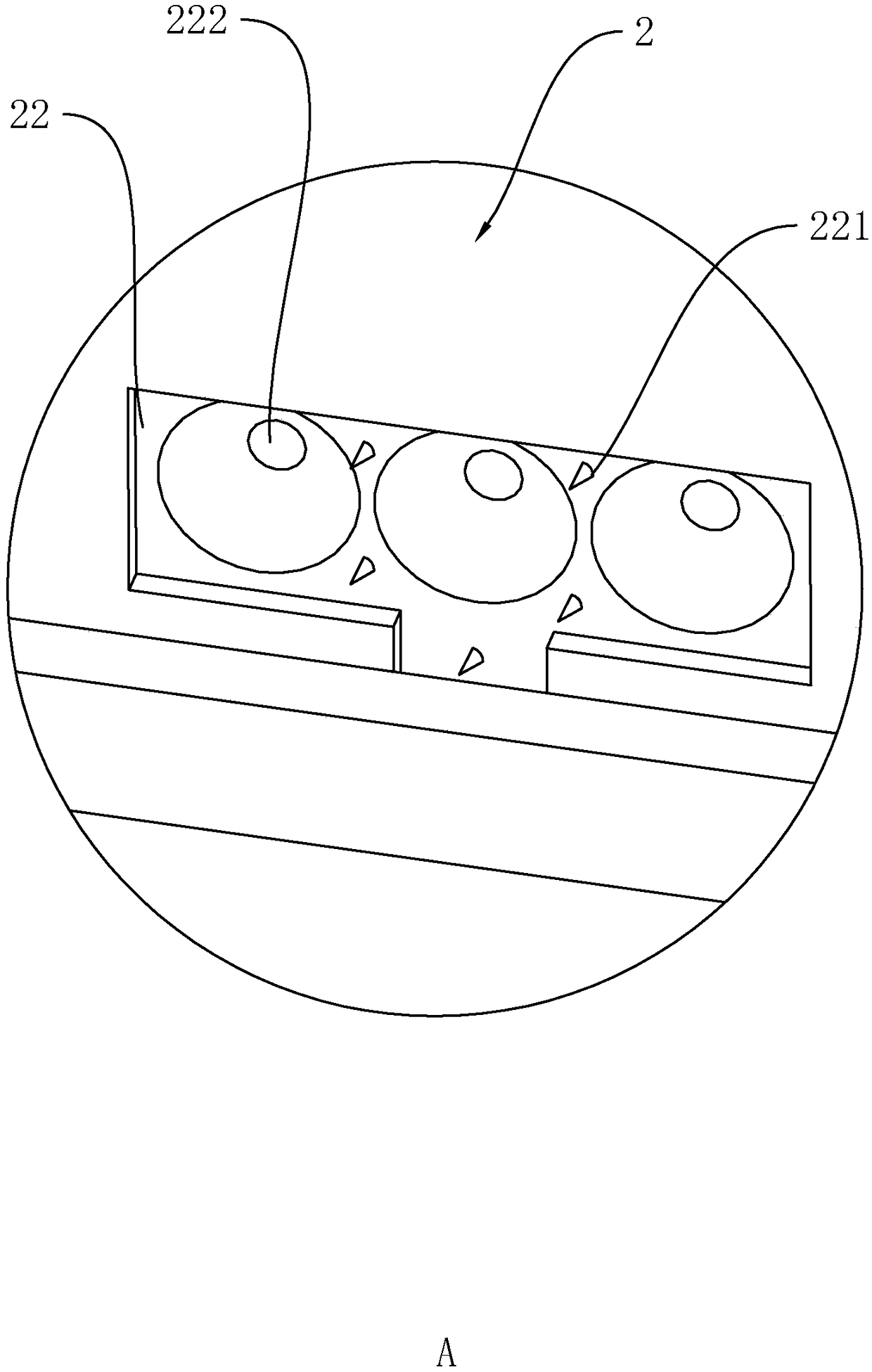
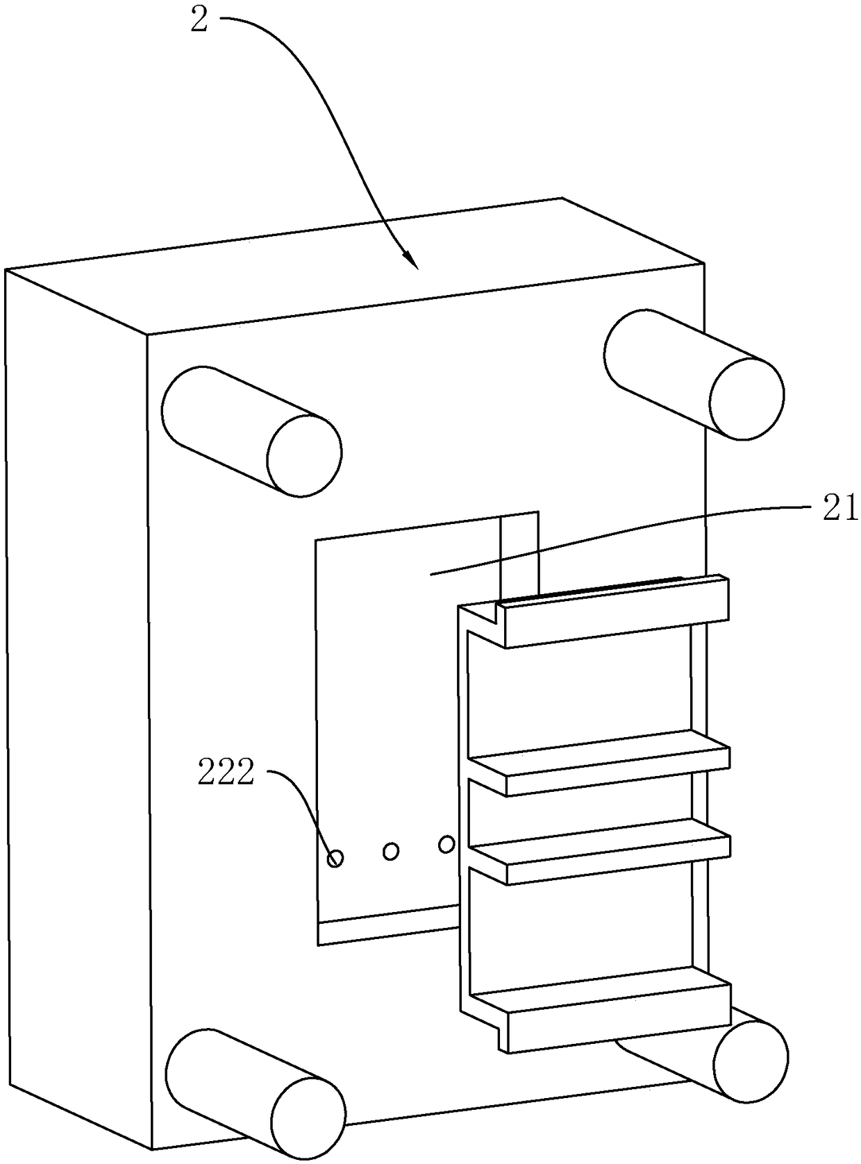
[0045] combine figure 1 with figure 2 , a first sliding positioning mechanism 11 is also provided between the front bottom plate 1 and the front formwork 2, and the first sliding positioning mechanism 11 adopted in this embodiment is a positioning guide sleeve and a positioning guide post (here is a prior art Not to repeat), the sliding positioning of the front formwork 2 relative to the front base plate 1 can be completed through the first sliding positioning mechanism 11 , and the side of the front base plate 1 away from the front formwork 2 is also provided with a main gate 12 . The front formwork 2 is provided with a die cavity 21 on one side away from the front bottom plate 1 (refer to image 3 ), the side of the front formwork 2 close to the fr...


PUM


Abstract

The invention discloses an injection mold with an automatic waste discharging function, and relates to the field of injection molding machines. The injection mold comprises a front base plate and a front mold frame. A sprue groove is formed in the side, close to the front base plate, of the front mold frame. A plurality of branched sprues are formed in the sprue groove. Sliding columns are connected to the side, close to the front mold frame, of the front base plate. A cavity is formed in the front mold frame. A swing rod is rotatably connected into the cavity. Strip-shaped grooves are formedin the swing rod. The sliding columns are fixedly connected with short columns inserted into the strip-shaped grooves. An arc-shaped block is fixedly connected to the lower end of the swing rod. A slitting plate is slidably connected into the cavity. Annular knives are separately arranged at the positions, corresponding to the branched sprues, of the slitting plate. The upper end of the slitting plate abuts against the arc-shaped block. A push rod is also slidably connected into the cavity. One end of the push rod can extend into the sprue groove, and the other end of the push rod abuts against the arc-shaped block. By adoption of the injection mold, the problem that in the prior art, waste in a sprue is difficult to remove is solved, and waste in sprue of the injection mold can be discharged automatically.

Description

technical field [0001] The invention relates to the field of injection molding machines, in particular to an injection mold for automatically removing waste materials. Background technique [0002] Injection mold is a tool for producing plastic products; it is also a tool for giving plastic products complete structure and precise dimensions. Injection molding is a processing method used in the mass production of certain complex-shaped parts. Specifically, it refers to injecting the heated and melted plastic into the mold cavity under high pressure from the injection molding machine, and after cooling and solidifying, a molded product is obtained. [0003] Existing reference can be made to the Chinese utility model patent document whose authorized announcement number is CN207105469U, which discloses an injection mold for automatically removing waste, including an upper injection mold and a lower injection mold. The lower surface of the upper injection mold is formed with a l...

Claims


Application Information

Patent Timeline
Patent Type & Authority Applications(China)
IPC IPC(8): B29C45/26B29C45/17B29C45/38B29C45/40
CPCB29C45/1769B29C45/26B29C45/38B29C45/4005
Inventor 方楷
Owner SHENZHEN CARES PLASTIC ELECTRONICS
Why Eureka
Try Eureka